Device for continuous production of plate-shaped products

a technology of plate-shaped products and holder, which is applied in the direction of dough shaping, press rollers, baking, etc., can solve the problems of insufficient friction locking, inability to ensure the required exact positioning of the strips, and complicated and expensive use of a holder of this kind

Inactive Publication Date: 2001-11-27
VALMET PANELBOARD
View PDF11 Cites 5 Cited by
  • Summary
  • Abstract
  • Description
  • Claims
  • Application Information

AI Technical Summary

Problems solved by technology

A material flow of this kind would moreover lead to the respective design structure being disturbed in the product edge region and to this edge region thus becoming unusable.
In practice, however, the resulting frictional locking is not sufficient in order to ensure the required exact positioning of the strips, in particular when a high internal pressure arises in the pressing gap as a result of the ma

Method used


Image

  • Device for continuous production of plate-shaped products
  • Device for continuous production of plate-shaped products
  • Device for continuous production of plate-shaped products

Examples


Embodiment Construction

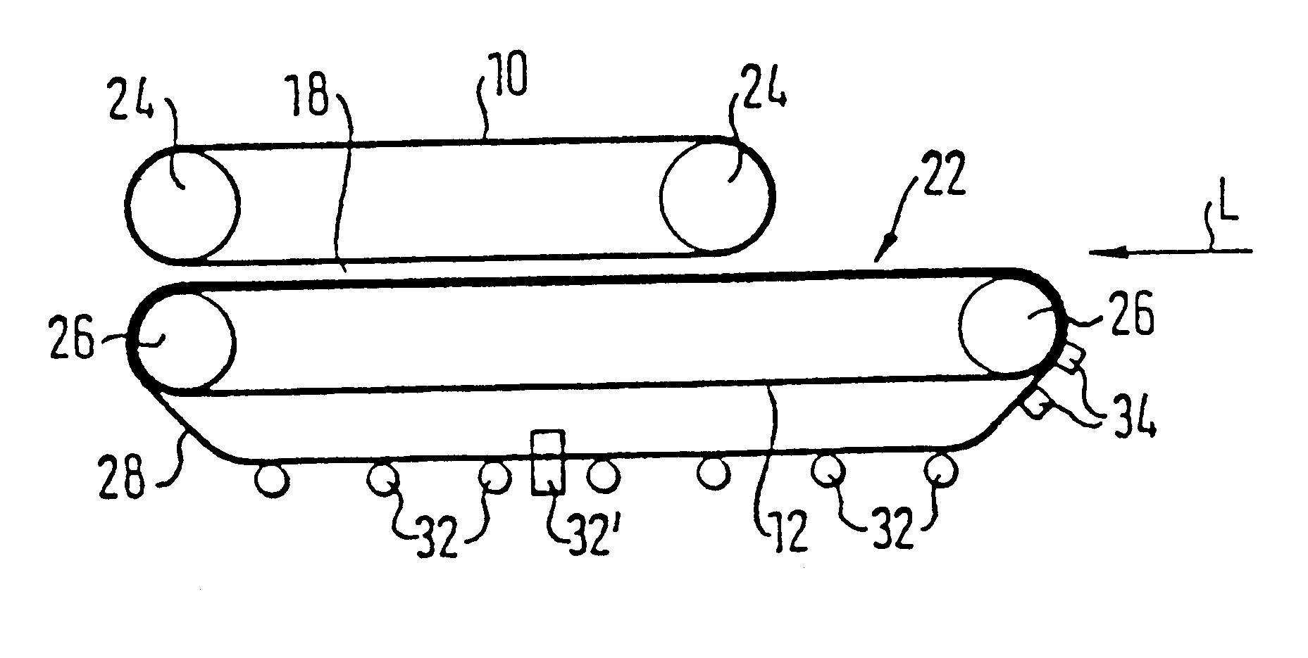
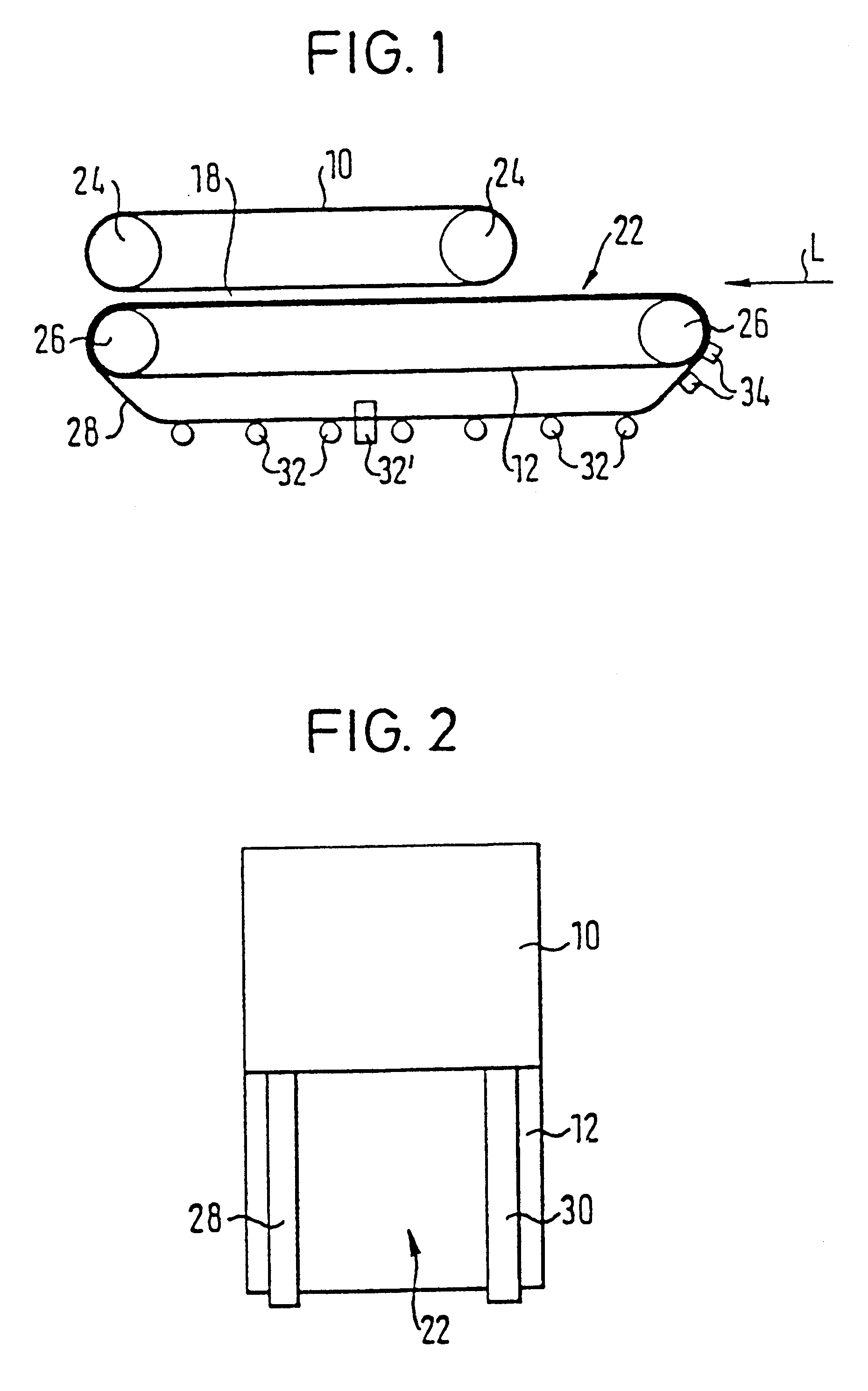
FIG. 1 shows in a purely schematic side view a device for continuous production of plate-shaped products.

As can be recognized with reference to FIGS. 2 to 4, the device comprises two endless strips 10, 12 which are positioned one above the other and can be driven via support surfaces 14, 16. A working gap 18 is defined between mutually adjacent sides of the endless strips. A starting material 20 for processing, which is first deposited onto the upper side of the lower endless strip 12 in the input region 22, is conveyed in the strip travel direction L through working gap 18.

The endless strips 10, 12, which for example consist of steel, are in each case guided around two rollers 24 and 26 respectively which are arranged with a spacing with respect to one another.

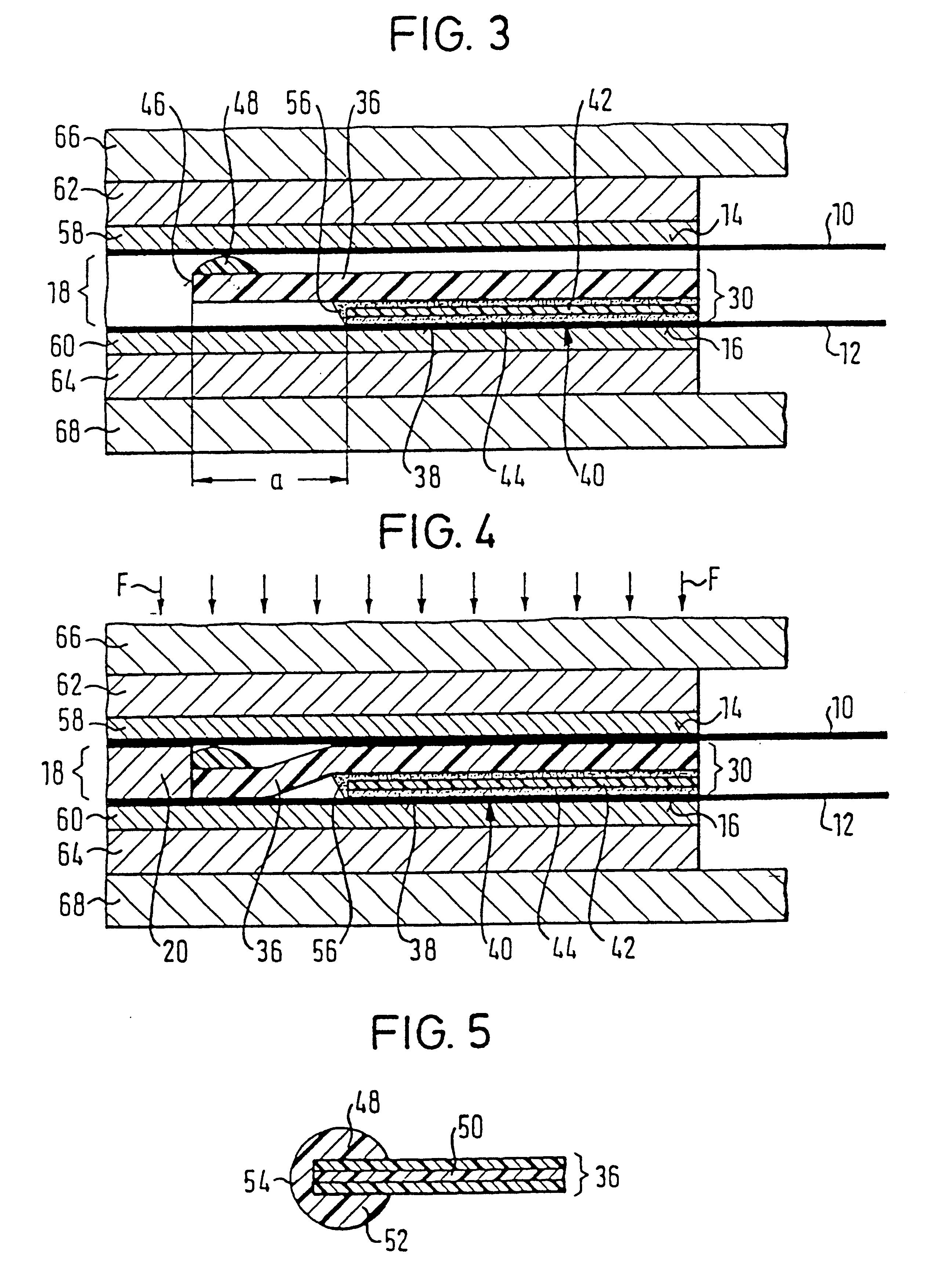
The working gap 18 is bounded on each side by an accompanying strip 28, 30 (cf. in particular FIG. 2), of which only one can be recognized in each case in FIGS. 1, 3 and 4.

Two accompanying strips 28, 30 in each case encircle ...


PUM

PropertyMeasurementUnit
Temperatureaaaaaaaaaa
Flexibilityaaaaaaaaaa
Adhesivityaaaaaaaaaa

Abstract

The invention relates to a device for the continuous production of plate-shaped products, comprising two endless strips which are positioned one above the other and can be driven. A working gap is formed between the sides of said endless strips, said sides being adjacent to one another and each being conveyed via a support surface. The starting material for processing is conveyed through said working gap which is bordered on each side by an accompanying strip. Said accompanying strip is situated along said working gap between the two endless strips and moves with them, consisting of a flexible sealing strip which has a friction surface on at least one face, said face facing towards an endless strip. Said friction surface increases the static friction between the flexible sealing strip and the endless strip.

Description

1. Field of the InventionThe invention relates to a device for continuous production of plate-shaped products.2. Description of the Prior ArtIn the compression of materials which achieve the liquid phase or are softened during the compression process, accompanying strips are required, through which a lateral flowing away of the product is prevented. A lateral flowing away of the product would namely mean that the counter pressure drops in the product edge region and that an isobaric compression pressure no longer prevails there. A pressure decrease would set in toward the edge which further favors the flow process. A material flow of this kind would moreover lead to the respective design structure being disturbed in the product edge region and to this edge region thus becoming unusable.A device for continuous production of plate-shaped products, which has co-moving strips of elastic material for the lateral closing off of the working gap of the described device, is known from EP 048...

Claims


Application Information

Patent Timeline
IPC IPC(8): B30B5/06B30B5/00
CPCB30B5/06
Inventor HOFFMANN, PETERHAUPT, ULRICH
Owner VALMET PANELBOARD
Why Eureka
Try Eureka