Color display apparatus

a display apparatus and color technology, applied in the field of color display apparatuses, can solve the problems of posing a limitation in the increase of display density, posing a certain limit in providing an increased display density, and still insufficien

Inactive Publication Date: 2001-12-04
CANON KK
View PDF11 Cites 187 Cited by
  • Summary
  • Abstract
  • Description
  • Claims
  • Application Information

AI Technical Summary

Problems solved by technology

However, in view of the necessity of driver loading according to the TCP scheme or bare chip loading scheme, the electrode pitch has to be a certain value or larger, thus posing a limitation in increase of display density.
In the case of bare chip loading, an electrode pitch smaller than 60 .mu.m is allowed, but still a certain limit is posed in providing an increased display density.
120 .mu.m which is smaller than that in the case of FIG. 2 but is still insufficient.
Further, the arrangement shown in FIG. 12 or FIG. 13 uses a sub-pixel G or a sub-pixel W in addition to three sub-pixels of primary colors R, G and B, thus being accompanied with a difficulty of inferior color purity.

Method used


Image

  • Color display apparatus
  • Color display apparatus
  • Color display apparatus

Examples


example 1

In this Example, one pixel requires 2 data electrodes 9b (n=2) so as to satisfy 1

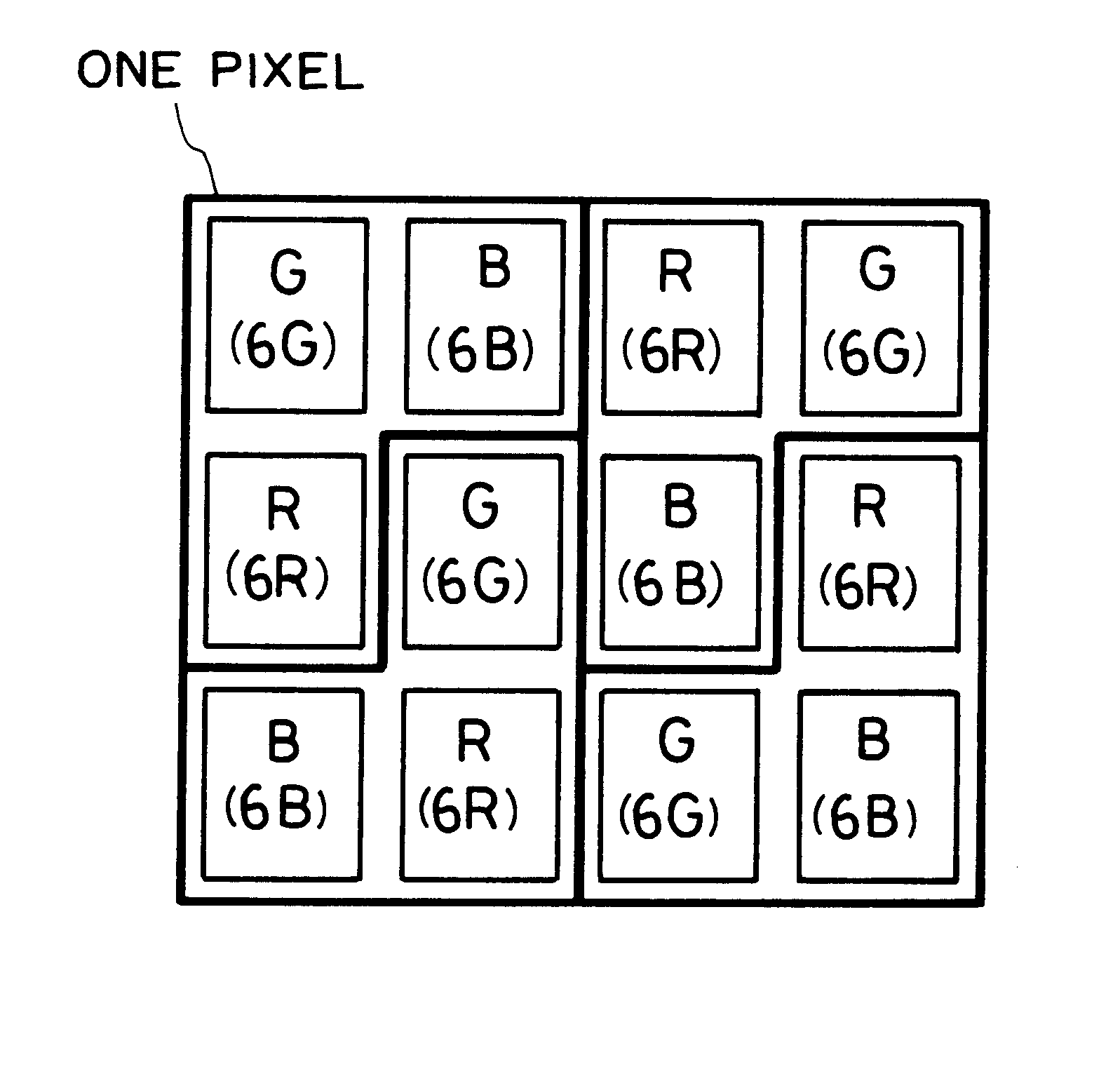
More specifically, as shown in FIG. 5A, for adjacent 3 scanning electrodes (a first scanning electrode 9a.sub.n, a second scanning electrode 9a.sub.n+1 and a third scanning electrode 9a.sub.n+2), first-color and second-color color filter segments 6R and 6G are alternately disposed along the first scanning electrode 9a.sub.n ; third-color and first-color color filter segments 6B and 6R are alternately disposed along the second scanning electrode 9a.sub.n+1 ; and second-color and third-color color filter segments 6G and 6B are alternately disposed along the third scanning electrode 9a.sub.n+2 ; so that as shown in FIG. 5B, one pixel is first-color and second-color color filter segments 6R and 6G along the first scanning electrode the first scanning electrode 9a.sub.n, and a third-color color filter segment 6B along the second scanning elect...

example 2

In this Example, one pixel requires 3 / 2 data electrodes 9b (n=3 / 2), satisfying 1

More specifically, as shown in FIG. 6A, first-color to third-color color filter segments 6R, 6G and 6B are disposed in this order along the first scanning electrode 9a.sub.n on the second scanning electrode 9b.sub.n+1, respectively, but with one color filter segment shifted along the second scanning electrode 9a.sub.n+1, so that the third color filter segment 6B along the second scanning electrode 9a.sub.n+1 is disposed adjacent to the first color filter segment 6R along the first scanning electrode 9a.sub.n ; whereby as shown in FIG. 6B, one pixel is composed of first color and second-color color filter segments 6R and 6G along the first scanning electrode 9a.sub.n and a third-color color filter segment 6B along the second scanning electrode 9a.sub.n+1, and another one pixel is composed of a third-color color filter segment 6B along the first scanning electrode 9a...

example 3

In this Example, one pixel requires 2 data electrodes 9b (n=3 / 2), satisfying 1

More specifically, as shown in FIG. 7A, first-color and second-color color filter segments 6R and 6G are disposed alternately along a first scanning electrode 9a.sub.n, and third-color color filter segments and disposed in succession along a second scanning electrode 9a.sub.n+1, while the third-color color filter segments 6B are designed to have an area which is a half that of each of the first-color and second-color color filter segments 6R and 6G. Further, one pixel is composed of first-color and second-color color filter segments 6R and 6G and two third-color color filter segments 6B. Consequently, 4 pixels are formed by 4 data electrodes 9b and 4 scanning electrodes 9a in this Example.

On the other hand, a liquid crystal panel is designed to have a diagonal size of 15 inches with a vertical / lateral ratio of 4 / 3 (a vertical size of 12 inches and a lateral size of 9...


PUM

PropertyMeasurementUnit
vision distanceaaaaaaaaaa
colorsaaaaaaaaaa
coloraaaaaaaaaa

Abstract

A color display apparatus, such as a color liquid crystal display apparatus, is composed of a multiplicity of sub-pixels each designed for displaying one of a plurality (k) of mutually different mono-colors and arranged in rows and columns so as to form pixels each with a plurality of mutually adjacent sub-pixels. The sub-pixels and pixels are so arranged that a number n given by dividing a total number of sub-pixels arranged in a row or column with a total number of pixels arranged in the row or column is set to satisfy: 1<n<k, wherein k denotes the plurality of the mono-colors displayed by the sub-pixels. As a result, the pixel pitch can be reduced to provide an increased display density and an improved display quality.

Description

FIELD OF THE INVENTION AND RELATED ARTThe present invention relates to a color display apparatus for effecting multi-color display by combination of ON / OFF of neighboring sub-pixels.Hitherto, various color display apparatus have been used, inclusive of a liquid crystal device (liquid crystal panel) aligned with a color filter and light-emitting device (LED).FIG. 1 is a sectional view of an example of conventional liquid crystal panel structure. Referring to FIG. 1, a liquid crystal panel P1 includes a pair of mutually oppositely disposed substrates 1a and 1b, which are applied to each other with a sealing member 2 to leave a gap that is filled with a liquid crystal 3.A surface of one substrate 1a is provided with a multiplicity of stripe-shaped scanning electrodes 9a which are coated with an insulating film 10a and an alignment film 11a.A surface of the other substrate 1b is provided with color filters or color filter segments 6 of three colors, i.e., R (red), G (green) and B (blue)...

Claims


Application Information

Patent Timeline
Patent Type & Authority Patents(United States)
IPC IPC(8): G02F1/1335G02F1/13G02F1/1343G09F9/30
CPCG02F1/133514G02F2001/134345G02F2201/52G09G2300/0452G02F1/134345
Inventor MORI, HIDEOTATSUMI, EISAKUMATSUBAYASHI, KAZUHIROTAKAHASHI, MASANORIKANDA, TOSHIYUKI
Owner CANON KK
Why Eureka
Try Eureka