Arrangement and method for inspection of surface quality

a technology of surface quality and arrangement, applied in the direction of material analysis, instruments, computer peripheral equipment, etc., can solve the problems of inability to adjust to a change in the surface material, inability to adjust, and inability to adjust, so as to enhance the inspection of glossiness and reflectivity of the surface, and enhance the analysis of 3d characteristics

Inactive Publication Date: 2001-12-04
THERMO RADIOMETRIE +1
View PDF17 Cites 125 Cited by
  • Summary
  • Abstract
  • Description
  • Claims
  • Application Information

AI Technical Summary

Benefits of technology

Various advantages are achieved with the method and arrangement of the invention. The invention allows image analysis, in which the objects surface region, imaged while illuminated at different times with light beams from different illumination directions, is inspected. This enhances the analysis of the 3D characteristics of the surface considerably, since the object's surface region imaged while illuminated at different times with light beams from different illumination directions reveals more of its 3D characteristics than when it is illuminated simultaneously from different illumination directions. In addition to enhancing the analysis of the 3D characteristics, the non-simultaneous illumination also enhances inspection of the glossiness and reflectivity of the surface. The invention also allows the inspection of the surface of a fast moving o...

Problems solved by technology

The fact that the 3D analysis is based on color classification impairs the method: for example, the method is not able to adjust to a change in the surface material of the object's surface, in which the surface material changes either completely or changes to a different variety of the same surface materia...

Method used


Image

  • Arrangement and method for inspection of surface quality
  • Arrangement and method for inspection of surface quality
  • Arrangement and method for inspection of surface quality

Examples


Embodiment Construction

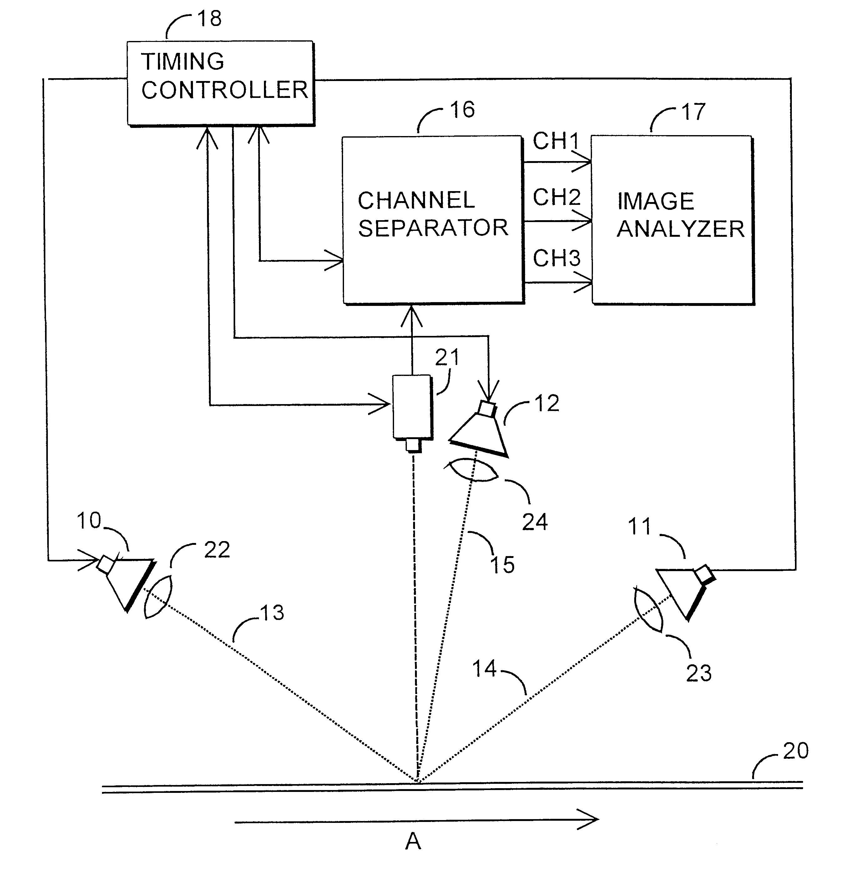
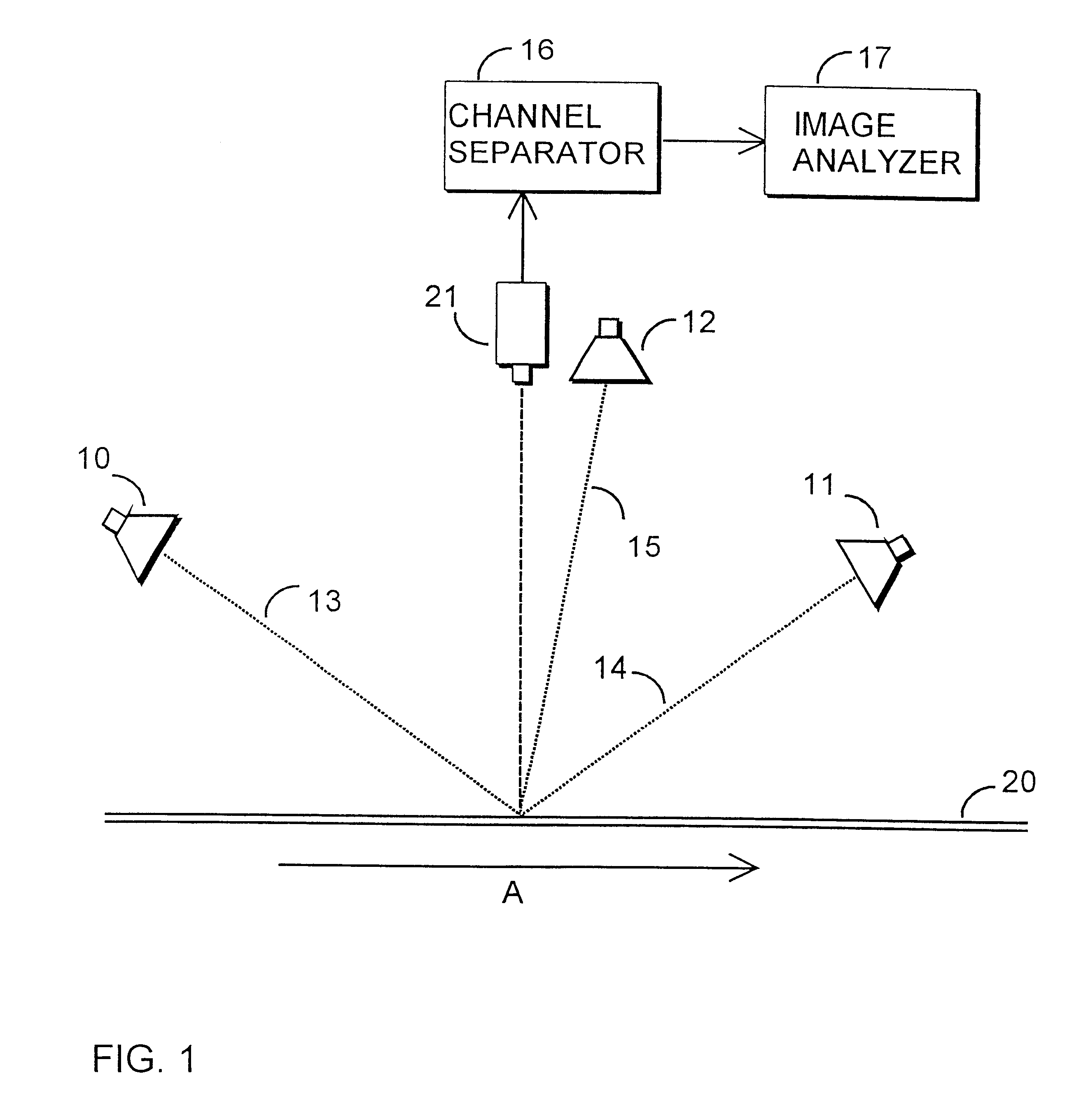
FIG. 1 shows an arrangement for inspecting the quality of a surface 20 of a moving object. The movement of the object is indicated by arrow A. In a preferred embodiment the surface inspected is a strip-like surface or a sheet-like surface, for example a surface of a rolled metal product. The arrangement comprises light sources 10-12 of at least two--in the figure, three--illumination directions 13-15 for illuminating a region on the object's surface, and a line scan camera 21 for imaging the illuminated surface region. The arrangement further comprises a channel separator 16 for performing channel separation on the output signal of the line scan camera 21, and a image analyzer 17 for analyzing the image information obtained from the channel separator.

In FIG. 1 the surface 20 of the moving object is illuminated with light sources 10-12 of at least two different illumination directions 13-15. The illuminated region on the object's surface is imaged with the line scan camera 21, and th...


PUM


Abstract

The invention relates to a method for automatic inspection of the surface 20 of a moving object, in which a region on the object's surface is illuminated from at least two different illumination directions 13-15. The object's illuminated surface region is imaged with a camera to provide image information for analysis. The light sources in the different illumination directions 13-15 are pulsed to illuminate the object's surface region at different times, the pulsing frequency being >1 kHz The object's illuminated surface region is imaged as lines with a line scan camera 21 in sync with the above pulsing. The invention also relates to an arrangement for inspecting the surface 20 of a moving object, the arrangement comprising at least two light sources 10-12 in at least two different illumination directions 13-15 for illuminating the surface region of the object under inspection; a camera for imaging the object's surface region; and an image analyzer for analyzing the image information acquired from the object's surface 20 by imaging. The light sources 10-12 illuminate the object's surface 20 from the different illumination directions 13-15 at different times, and the camera is a line scan camera 21. The arrangement further comprises a timing controller 18 for synchronous pulsing of the light sources 10-12 and the at least one line scan camera 21, the pulsing frequency of the light sources 10-12 being >1 kHz.

Description

The invention relates to inspection of strip-like or sheet-like surfaces, such as surfaces of rolled metal products, by an optoelectronic measuring arrangement.BACKGROUND OF INVENTIONDE 19 511 534 A1 teaches a prior art method and arrangement in which the 3D characteristics of a moving surface are inspected by illuminating the surface from at least two different illumination directions with light sources, the light sources of each illumination direction illuminating the surface with a light of a different color than the other illumination directions. The object's surface is illuminated simultaneously from the different illumination directions, and the so illuminated surface is imaged with a camera to provide image information for analysis. The analysis of the 3D characteristics of the object's surface is based on color classification, with which the color values detected on the surface are compared.The prior art method and arrangement allow the inspection of the 3D characteristics o...

Claims


Application Information

Patent Timeline
IPC IPC(8): G01B11/30G01N21/57G01N21/55G01N21/88G01N21/89G01N21/892G01N21/93
CPCG01B11/303G01N21/57G01N21/8903
Inventor PIIRONEN, TIMO H.PAUL, DETLEFKONTIO, PERTTI
Owner THERMO RADIOMETRIE
Why Eureka
Try Eureka