

Fastener with anti-cross-threading point and method of assembly
a technology of threaded fasteners and anti-cross threading, which is applied in the direction of threaded fasteners, fastening means, screws, etc., and can solve problems such as and inability to meet the requirements of assembly
- Summary
- Abstract
- Description
- Claims
- Application Information
AI Technical Summary
Benefits of technology
Problems solved by technology
Method used
Image

Examples
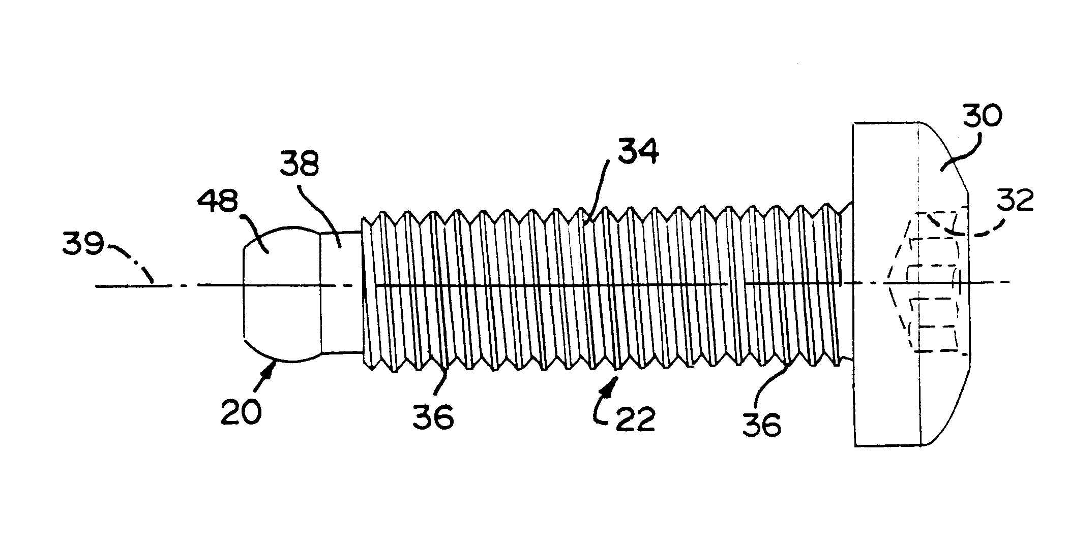
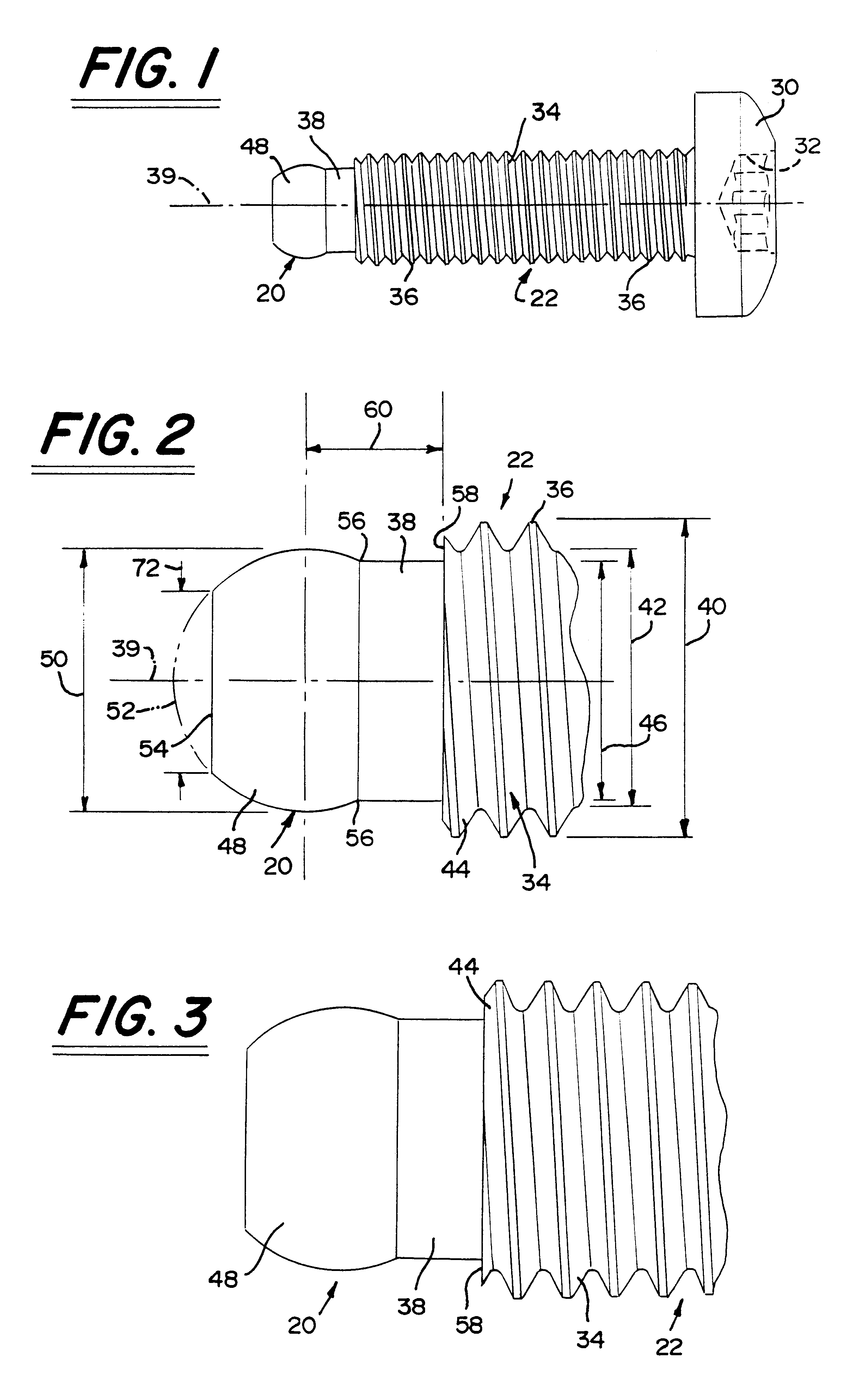
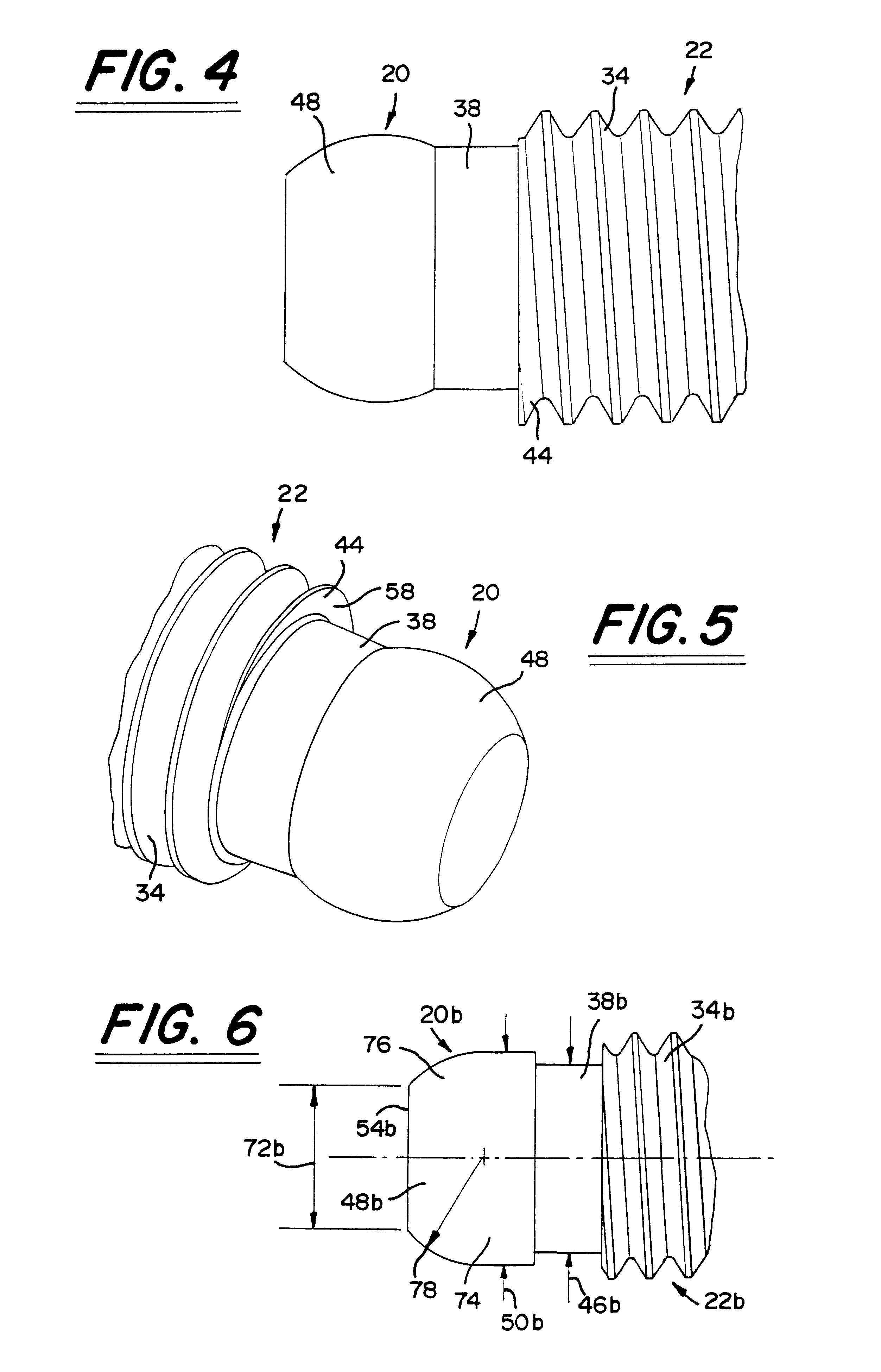
first embodiment
the novel point 20 on the fastener member 22 is shown in FIGS. 1-5. A second embodiment of the novel point 20b is shown in FIG. 6; a third embodiment of the novel point 20c is shown in FIG. 7; a fourth embodiment of the novel point 20d is shown in FIG. 8; and a fifth embodiment of the novel point 20e is shown in FIG. 9. Like elements in each embodiment are denoted with like reference numerals with the second embodiment having the suffix "b" after the reference numeral; the third embodiment having the suffix "c" after the reference numeral; the fourth embodiment having the suffix "d" after the reference numeral; and the fifth embodiment having the suffix "e" after the reference numeral.
FIGS. 10-14 and 15-18 illustrate the fastener member 22 shown in FIGS. 1-5 being inserted in an out-of-alignment or off-angle installation into the female member 68, 98. FIGS. 19-22 illustrate the fastener member 22 shown in FIGS. 1-5 being inserted in an offset (as opposed to an off-angle orientation)...
third embodiment
the fastener member 22c is shown in FIG. 7. The fastener member 22c includes the novel point 20c on one end of the threaded shank portion 34c. In this embodiment of the fastener member 22c, the cylindrical portion 38 which is shown in the other embodiments has been eliminated and instead, the bulbous portion 48c is directly connected to the end of the threaded shank portion 34c. The bulbous portion 48c is formed from a radiused portion 80 defined by radius 82. A truncated end surface 54c is provided at the end of the radiused portion 80 and defines a diameter 72c.
fourth embodiment
the fastener member 22d is shown in FIG. 8. The fastener member 22d includes the novel point 20d on one end of the threaded shank portion 34d. The bulbous portion 48d of the point 20d has a first radiused portion defined by radius 84, a second radiused portion defined by radius 86, a third radiused portion defined by radius 88 and a fourth radiused portion defined by radius 90. A truncated end surface 54d is provided at the end of the radiused portion defined by radius 90 to define a diameter 72d.
With respect to the specifics of the fifth embodiment of the fastener member 22e having the novel point 20e on one end of the threaded shank portion 34e which is shown in FIG. 9, the bulbous portion 48e of the point 20e has a first radiused portion defined by radius 92, a second radiused portion defined by radius 94, and a generally tapered portion defined by angle 96. A truncated end surface 54e defining a diameter 72e is provided at the end of the bulbous portion 48e.
In each of the embodi...
PUM
 Abstract
Description
Claims
Application Information