Tank weigh module with excess motion restraint

a technology of a weigh module and a motion restraint, which is applied in the direction of weighing apparatus details, weighing relieving/arresting mechanisms, instruments, etc., can solve the problems of excessive downward travel of the weigh module, excessive uplift travel, and the possibility of tilting or twisting motion of the weigh modul

Inactive Publication Date: 2001-12-18
HOTTINGER BALDWIN MEASUREMENTS
View PDF8 Cites 35 Cited by
  • Summary
  • Abstract
  • Description
  • Claims
  • Application Information

AI Technical Summary

Problems solved by technology

For example, if the vessel is subjected to wind loading, seismic tremors, or other forces that would cause a swaying or tilting of the tank, then the weigh modules arranged on one side of the tank are subjected to an excessive downward travel while the weigh modules arranged on the other side of the tank are subjected to an excessive uplift travel.
Under such circumstances, the weigh modules may also be subjected to tilting or twisting motions.
If such unusual and excessive motion is not checked or restrained, then the tank or other vessel could tip over.
The conventional provision of the above mentioned check rods, stays, overlift protection bolts, and the like has caused several disadvantages in the known tank weigh modules.
Most importantly, the overall construction of the...

Method used


Image

  • Tank weigh module with excess motion restraint
  • Tank weigh module with excess motion restraint
  • Tank weigh module with excess motion restraint

Examples


first embodiment

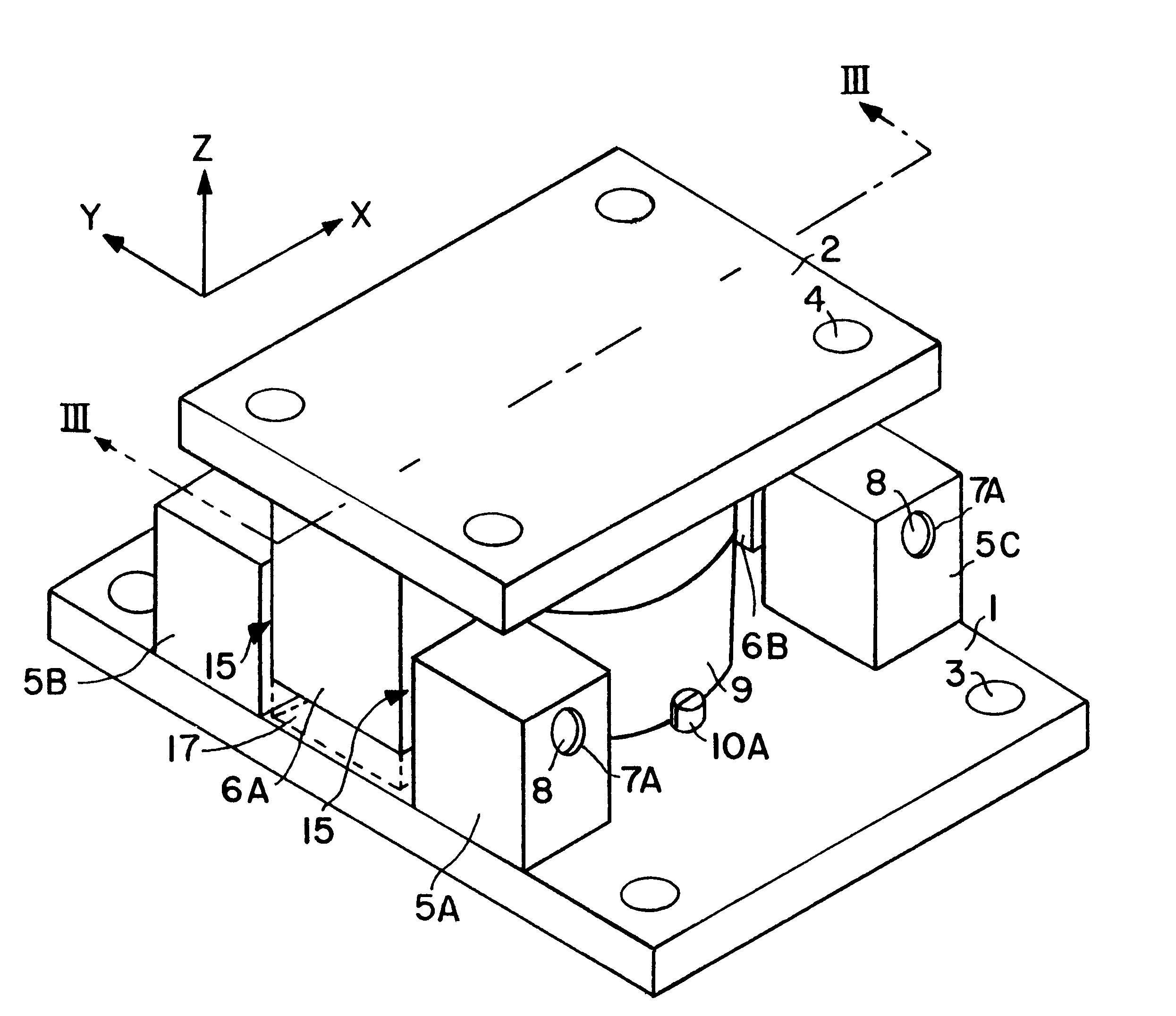
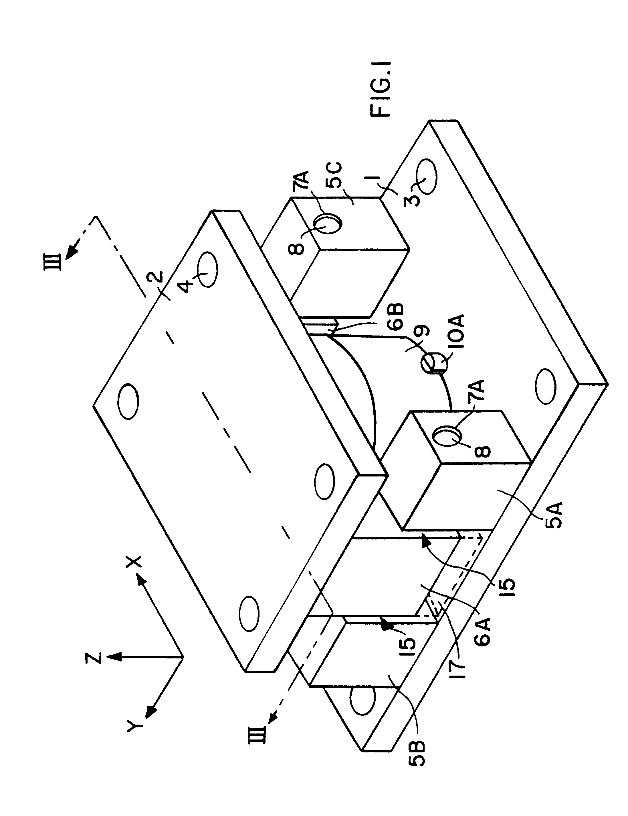
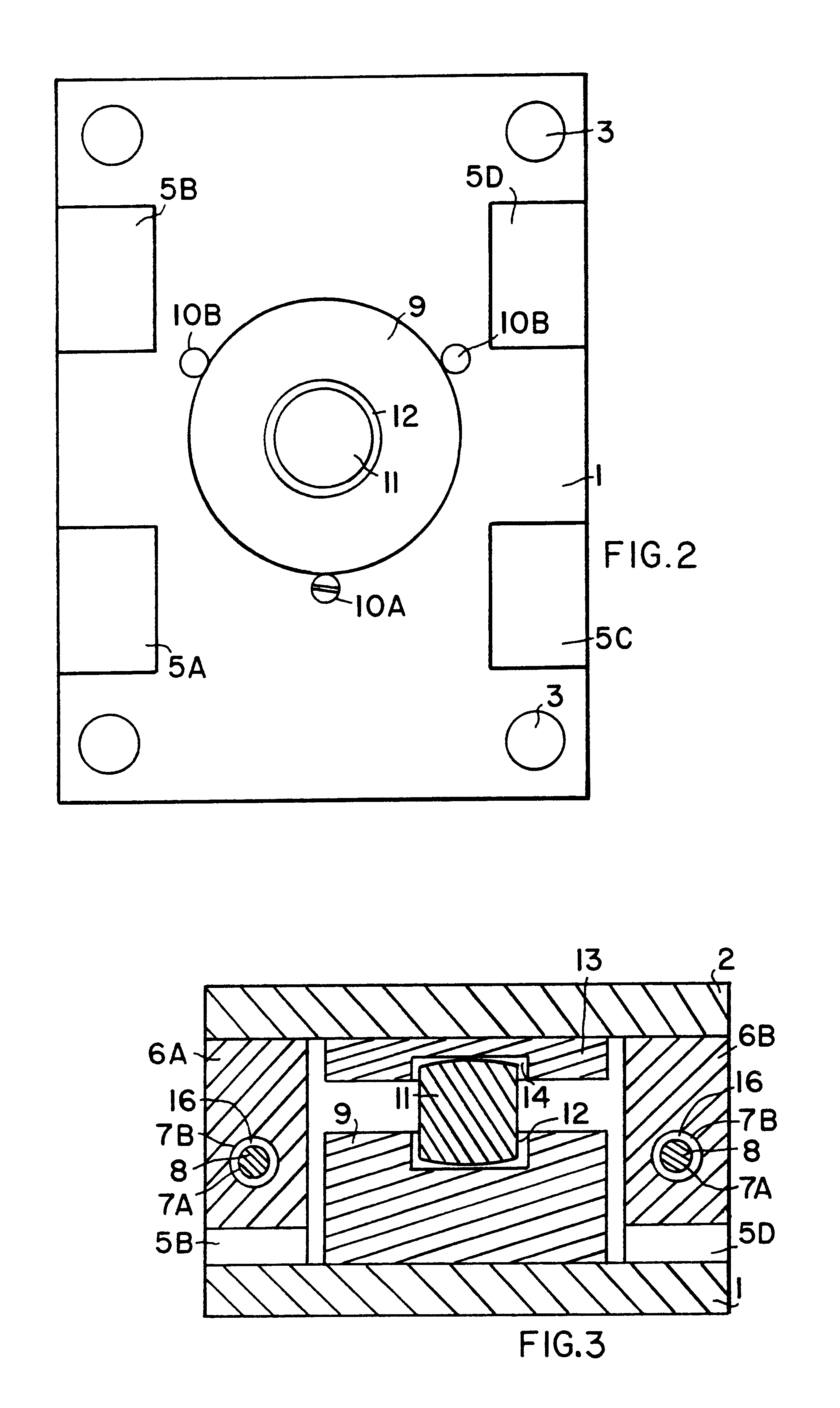
With reference to FIGS. 1, 2 and 3, a tank weigh module according to the invention includes a bottom plate 1 and a top plate 2 positioned substantially parallel to each other and spaced apart from each other, and adapted to receive a load cell 9 between the two plates 1 and 2. The bottom plate 1 has mounting holes 3 by which the plate 1 may be bolted to a supporting floor or the like. The top plate 2 has mounting holes 4 by which the plate 2 may be bolted to a supporting leg of a tank or other vessel, or any other item that is to be weighed. Typically, three or four of the present tank weigh modules will respectively be arranged and secured under the three or four legs of a tank or other vessel.

In order to provide the inventive free-floating, yet restrained connection between the top plate 2 and the bottom plate 1, the present embodiment comprises four lower stop blocks 5A, 5B, 5C and 5D connected (preferably welded) to the bottom plate 1 so as to protrude upwardly from the bottom p...

second embodiment

The distal or right-hand edge of the top plate 2 as shown in FIG. 4 is not connected to the bottom plate 1. Instead, the top plate 2 remains freely tiltable relative to the bottom plate 1, about the axis of the restraining pin 8, which acts as a hinge. Nonetheless, the present embodiment of the weigh module provides the desired range of free play motion, while preventing or restraining excessive motion in the back-and-forth Y-direction, the side-to-side X-direction, and the uplift Z-direction, as well as tilting about the X-axis and twisting about the Z-axis. A restraint against excess tilting about the Y-axis, i.e. about the axis of the restraining pin 8, is achieved by the cooperative arrangement of at least two of these weigh modules connected to the tank or other vessel being weighed. As long as the other weigh modules are not oriented in exactly the same orientation as the first weigh module, then a restraint of the tank in all possible motion and tilting directions will be ach...

third embodiment

Referring now to FIG. 5, the present weigh module comprises two lower stop blocks 5A and 5C connected to the bottom plate, two upper stop blocks 6A and 6B connected to the top plate 2, and two restraining pins 8, which are particularly embodied as restraining bolts 8'. In this embodiment, the restraining bolts 8' provide not only the restraining function in the positive and negative X-direction and the positive and negative Z-direction, but also in the positive Y-direction. Namely, when the top plate 2 moves in the negative Y-direction relative to the bottom plate 1, the upper stop blocks 6A and 6B will come to bear against the lower stop blocks 5A and 5C. However, since there are no lower stop blocks on the opposite sides of the upper stop blocks 6A and 6B, the restraining bolts 8' must somehow restrain the upper stop blocks 6A and 6B from excessive motion in the positive Y-direction.

This can be achieved in various ways. As shown on the left side of the weigh module in FIG. 5, the ...


PUM


Abstract

A tank weigh module includes a bottom plate that has two lower stop blocks protruding upwardly therefrom, and a top plate that has an upper stop block protruding downwardly therefrom into a space between the two upper stop blocks with a block free play clearance therebetween. A restraining pin is arranged to extend through aligned pin receiving holes in all of the stop blocks. In the lower stop blocks, the holes provide a tight friction fit for the pin, while the hole in the upper stop block has a larger diameter and provides a pin free play clearance. Motion of the top plate relative to the bottom plate in the back-and-forth Y-direction is limited to the extent of the block free play clearance. Travel of the top plate in the side-to-side X-direction and in the uplift Z-direction is restrained by the extent of the pin free play clearance. Tilting and twisting about the X-, Y-, and Z-axes are also limited by the pin interacting with the blocks and the blocks interacting with each other. A load cell is secured in position between the top and bottom plates by two fixed securing pins and a third removable securing pin attached to the bottom plate, whereby the securing pins are angularly offset by 120° from each other. The weigh module has a simple construction, installation, and servicing, and provides protection against excess uplift, side loading, and tilting while allow complete free floating operation in a normal operating range.

Description

The invention relates to a tank weigh module that is adapted to receive a load cell and that is provided with restraint features for preventing excess motion of the weigh module or the tank or other vessel mounted on the weigh module.BACKGROUND INFORMATIONTank weigh modules are generally known in the art for weighing material storage tanks, bins, hoppers and process vessels, so that the amount of material in the vessel can be determined. Typically, the entire weight of a tank or other vessel will be supported on three or four weigh modules respectively arranged between the three or four supporting legs of the vessel and the shop floor or other supporting platform. A typical tank weigh module is, in effect, a housing and interface adapted to receive a load cell and transmit the weight load of the vessel onto the load cell, which then carries out the weighing function. A conventional tank weigh module includes a base that can be bolted to the supporting floor, and a top plate that can...

Claims


Application Information

Patent Timeline
IPC IPC(8): G01G23/02G01G23/00
CPCG01G23/005G01G23/02
Inventor HOPKINS, RANDALL K.HANSSON, THOMAS W.
Owner HOTTINGER BALDWIN MEASUREMENTS
Why Eureka
Try Eureka