Optical polarization beam combiner/splitter

a technology of optical polarization beam and combiner, which is applied in the direction of optical elements, polarising elements, instruments, etc., can solve the problems of low extinction ratio and difficulty in managing fibers

Inactive Publication Date: 2001-12-18
II VI DELAWARE INC
View PDF11 Cites 23 Cited by
  • Summary
  • Abstract
  • Description
  • Claims
  • Application Information

AI Technical Summary

Problems solved by technology

It however, suffer s from several disadvantages, such as a larger device size necessitated by the need to employ an orthogonally disposed beam, suffer from a low extinction ratio, difficult to manage the fibers.

Method used


Image

  • Optical polarization beam combiner/splitter
  • Optical polarization beam combiner/splitter
  • Optical polarization beam combiner/splitter

Examples


Embodiment Construction

Persons of ordinary skill in the art will realize that the following description of the present invention is illustrative only and not in any way limiting. Other embodiments of the invention will readily suggest themselves to such skilled persons having the benefit of this disclosure.

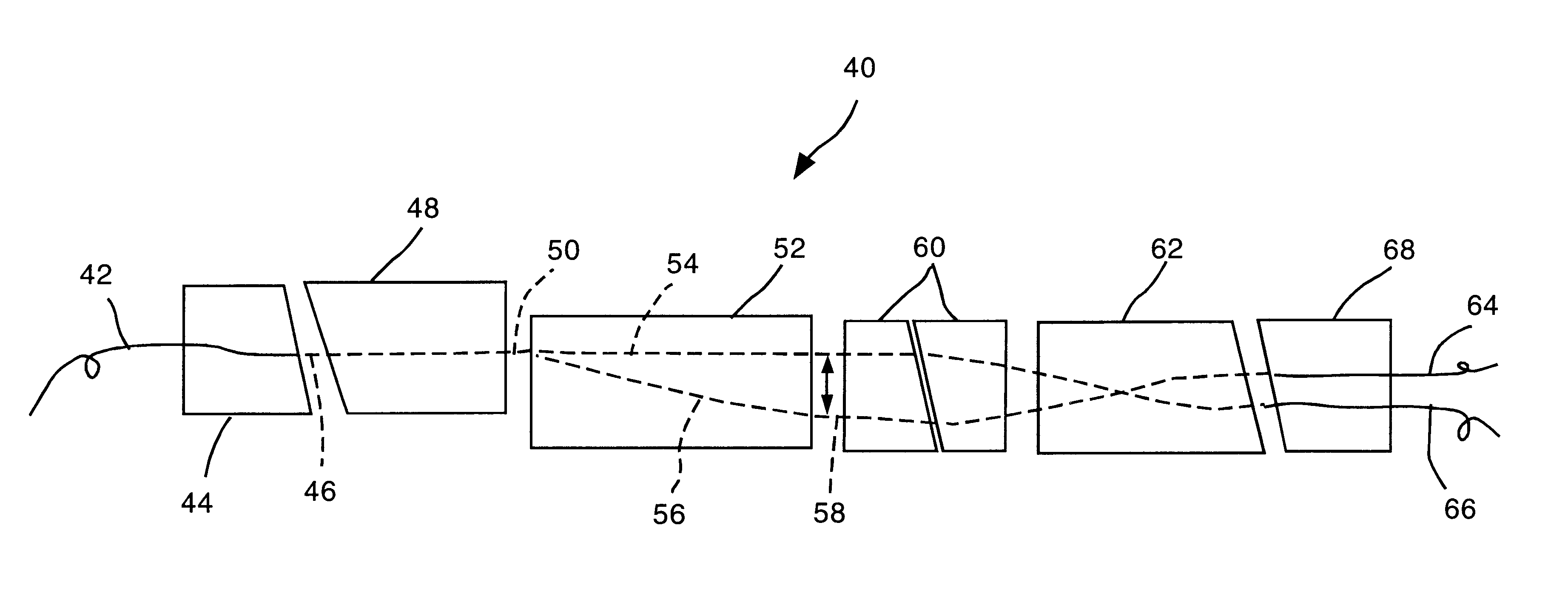
Referring now to FIG. 3, an optical block diagram of an embodiment of an optical polarized beam combiner / splitter 10 according to the present invention is shown. A first fiber ferrule 12 terminates fiber 14 at an angled face 16 thereof. Angled face 16 may be polished to an angle of about 8.degree. to 10.degree. as is the end of fiber 14, as is known in the art to avoid deleterious effects from internal reflections in the optical fiber. Fiber 14 carries a combined optical beam having a first component polarized in a first direction and a second optical beam polarized in a second direction orthogonal to the first direction. Fiber ferrule 12 may have a length in the optical path direction of about 4 mm.

A f...


PUM


Abstract

An optical polarization beam splitter comprises a first optical fiber having an end defining a first optical axis, a second optical fiber having an end defining a second optical axis, and a third optical fiber having an end defining a third optical axis parallel to and spaced apart from the second optical axis. A collimating lens is disposed along the first optical axis positioned to form a collimated optical beam from the first optical fiber. A focussing lens is disposed along a path of the collimated optical beam. A birefringent walk-off crystal has a first face adjacent to the focussing lens and a second face located at a focal plane of the focussing lens and in contact with the ends of the second and third optical fibers. The birefringent crystal is oriented such that and has a thickness between its first and second faces selected such that a first component of the optical beam having a first polarization exits the crystal at its second face and enters the end of the second optical fiber along the second optical axis and a second component of the optical beam having a second polarization orthogonal to the polarization of the first polarization exits the crystal at its second face and enters the end of the third optical fiber along the third optical axis.

Description

1. Field of the Invention2. The Prior ArtOptical polarization beam splitter / combiners are known in the art. These devices may be used in optical communication in many ways including, but not limited to, optical power multipliers for combining two optical pump beams to increase optical pumping power, in coherent optical communications applications, and as optical polarization division multiplexers.Two examples of prior art optical polarization beam splitter / combiners are shown in FIGS. 1A and 1B and FIGS. 2A and 2B, respectively. In the optical polarization beam splitter of FIG. 1A, an input beam enters from the fiber located at the left side of the figure. For the beam splitting operation, the incoming beam from fiber 1 at the left is collimated by the lens 1, and then enters the optical polarization beam splitter cube. The optical polarization beam splitter cube is able to split an arbitrary polarized light into two separated beams with orthogonally polarized directions. A first be...

Claims


Application Information

Patent Timeline
Patent Type & Authority Patents(United States)
IPC IPC(8): G02B6/34
CPCG02B6/2713G02B6/2773
Inventor HUANG, YONGLINXIE, PING
Owner II VI DELAWARE INC
Why Eureka
Try Eureka