Air-cooled condenser

a condenser and air technology, applied in steam/vapor condensers, heat exchange apparatuses, tubular elements, etc., can solve the problems of deteriorating the efficiency of heat transfer, freezing, and uncertainty of the congestion point, and achieve the effect of high efficiency of air-cooled condensers

Inactive Publication Date: 2001-12-25
ENERGIAGAZDALKODASI RESZVENYTARSASAG
View PDF19 Cites 34 Cited by
  • Summary
  • Abstract
  • Description
  • Claims
  • Application Information

AI Technical Summary

Benefits of technology

The main object of the invention is to provide an air-cooled condenser in which the inlet cross-section for the vaporous medium is as large as possible, in which even with a limited total finned tube cross section the steam-side pressure drop is relatively small, thereby making the temperature difference and the efficiency of the air-cooled condenser as high as possible, and from which the non-condensible gases are safely extracted.
According to another preferred embodiment the air-cooled condenser has a first part fitted with finned tubes each designed substantially symmetrically to a median plane bisecting the finned tubes perpendicularly to the side walls, and a second part fitted with finned tubes each having a separated after-cooler formed in a first channel in the direction of the air flow, the after-cooler being separated by a closure element arranged at an end of the first channel and by an adjoining continuous portion of a separation wall of the first channel from remaining parts of the finned tube, wherein in the first part one extraction pipe is connected to each of the finned tubes substantially at the median plane, in the second part one extraction pipe is connected to each of the first channels in the vicinity of said closure element, and the extraction pipes in the first part are connected via a common transfer pipe to each of the first channels of the finned tubes in the second part substantially at middle portions of the first channels. By means of this combination of finned tubes a very efficient air extraction can be provided.

Problems solved by technology

This air quantity--since the air is a non-condensible gas--is concentrated in the finned tubes of the condenser and deteriorates the efficiency of the heat transfer, i.e. at a given temperature difference less heat is transferred.
In cold weather it would result in the undercooling of the surface of the finned tube, which could cause freezing up of it.
Unfortunately, this is not the case, because this place could be different under various operating conditions.
In addition, not only the change in operating conditions, but also the inevitable flow asymmetry would also make the place of the congestion point uncertain.
The disadvantage in this case is that a significant heat quantity has to be removed from the steam-air mixture.
This air pockets, as mentioned above, may result in the freezing up of the finned tubes in cold weather.
Secondly, the friction loss of the cooling system will be increased for two reasons.
On the other hand, the path to be travelled by the steam is relatively long, and this is detrimental to the efficiency of the heat transfer.

Method used


Image

  • Air-cooled condenser
  • Air-cooled condenser
  • Air-cooled condenser

Examples


Embodiment Construction

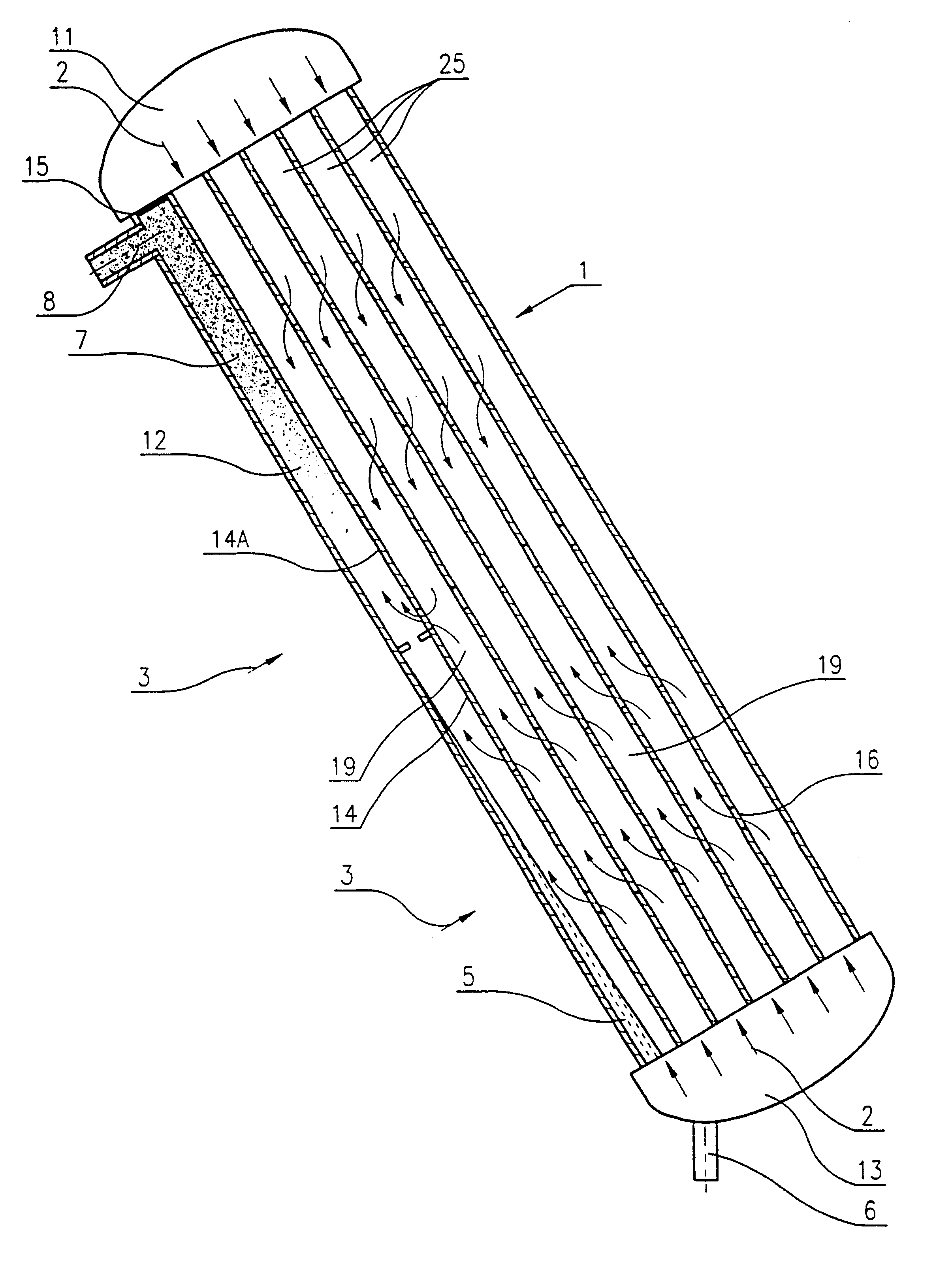
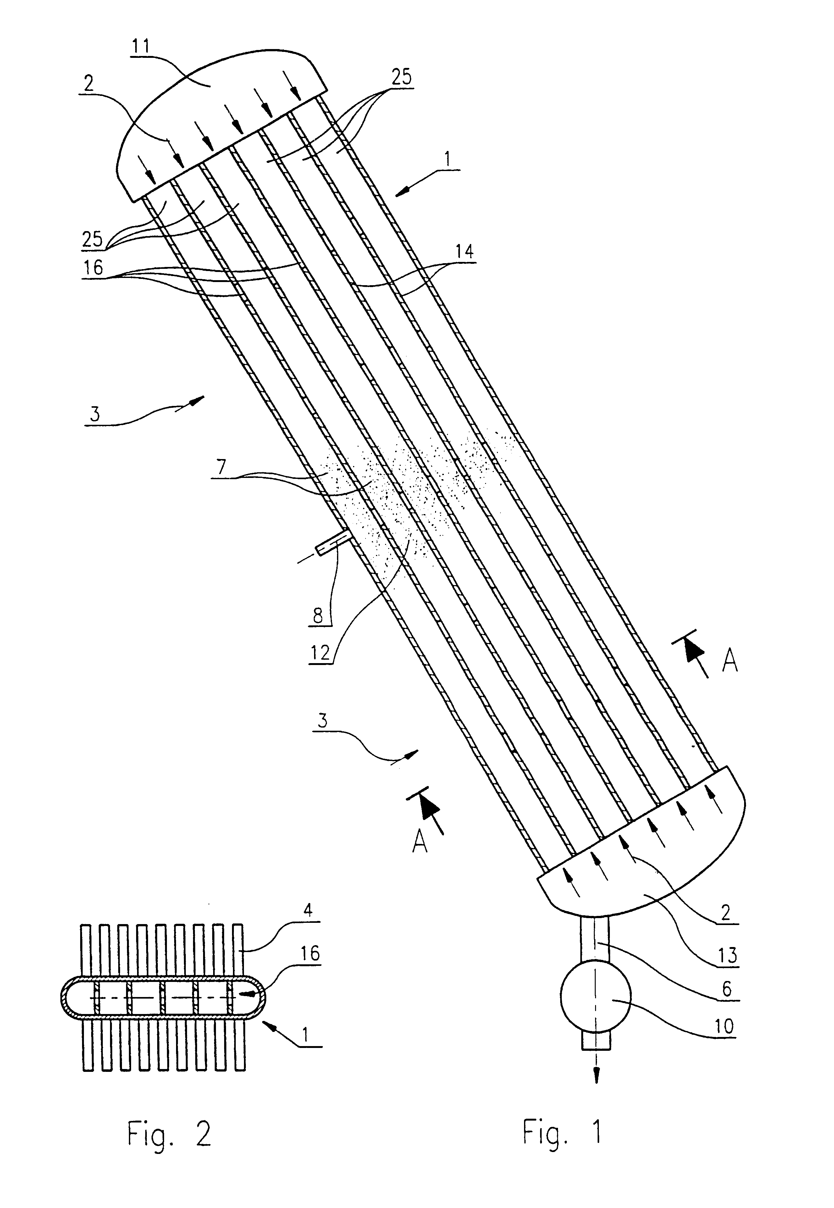
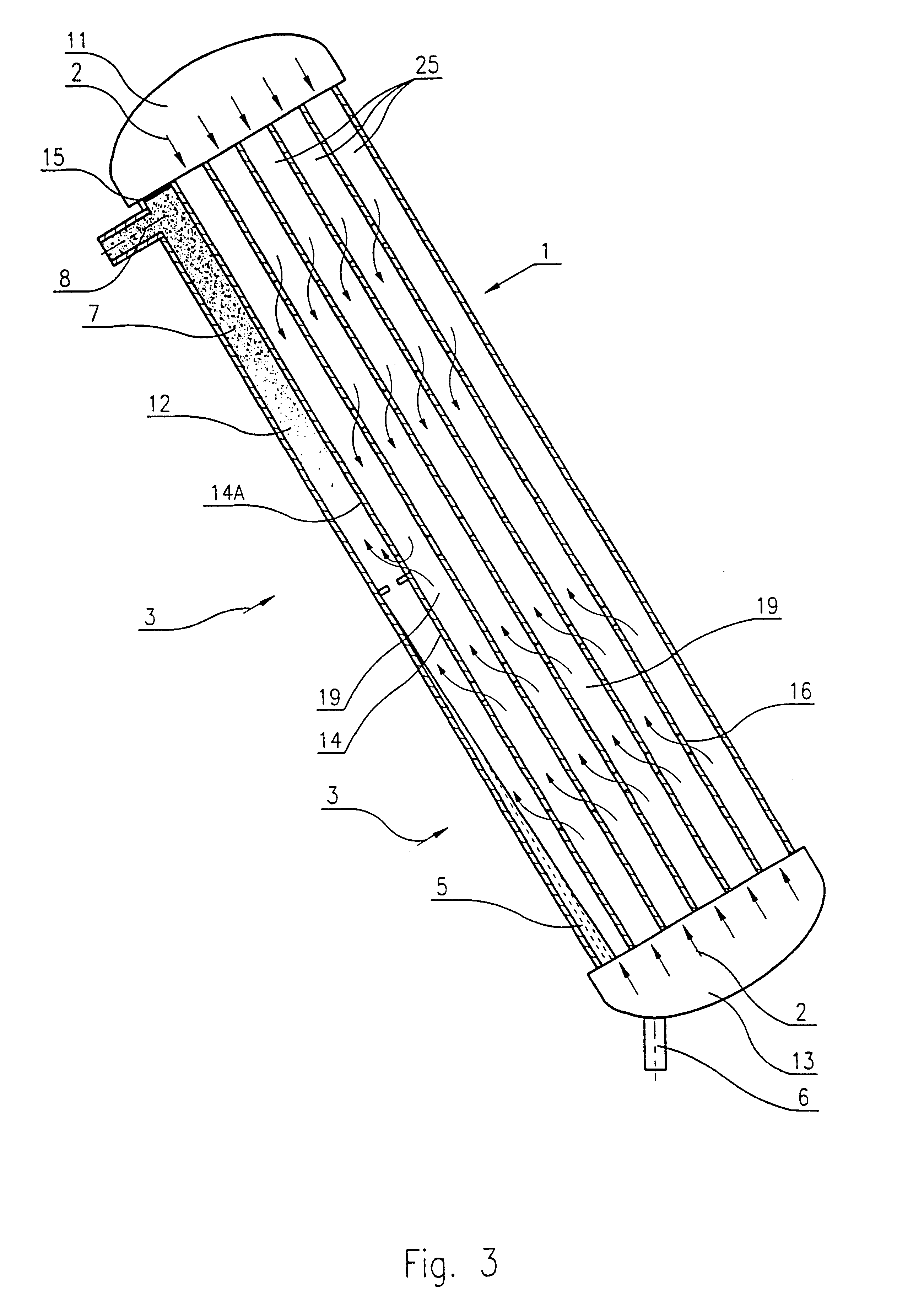
In FIG. 1 an air-cooled condenser is shown comprising an upper header 11, a lower header 13 and spaced finned tubes 1 connected in parallel between the upper header 11 and the lower header 13 and cooled by a cooling air flow 3. Condensate is drained from the lower header 13 via a drain pipe 6 by a pump 10.

In FIG. 1 one of the finned tubes 1 is shown in longitudinal cross-section. The transversal cross section of the finned tube 1 taken along plane A--A is depicted in FIG. 2. It can be seen that the finned tube has two parallel substantially flat side walls arranged in parallel to the cooling air flow 3 and opposite arched closing surfaces connecting the side walls. The finned tube 1 also has longitudinal separation walls 14 connected to the side walls and dividing the inner space of the finned tubes 1 into longitudinal parallel channels 25. In the separation walls 14 there are breakthroughs 16 for allowing the flow of the medium between neighbouring channels 25.In the depicted embod...


PUM


Abstract

An air-cooled condenser includes an upper header for distributing a vaporous medium to be condensed, a lower header for collecting condensate, spaced finned tubes with outer fins, the finned tubes being connected in parallel between the upper header and the lower header and cooled by a cooling air flow, means for draining the condensate form the lower header and extraction means for removing non-condensible gases from the condenser. The lower header is also used for distributing the vaporous medium to the finned tubes, so that the vaporous medium id fed into the finned tubes through both the upper and lower headers, and the extraction means are connected to each of the finned tubes at its portion facing the cooling air flow.

Description

The invention relates to an air-cooled condenser for condensing a vaporous medium, preferably steam, the condenser comprising an upper header for distributing the vaporous medium, a lower header for collecting condensate, spaced finned tubes with outer fins, said finned tubes being connected in parallel between the upper header and the lower header and cooled by a cooling air flow, means for draining the condensate from the lower header and extraction means for removing non-condensible gases from the condenser.Condensers are widely used in the manufacturing, chemical and energy industry. The direct system air-cooled condenser is a special type of condensers, which generally operates under vacuum and without cooling liquid, i.e. the vaporous medium is condensed directly by means of a cooling air flow.The air-cooled condensers usually consist of a number of finned tubes connected in parallel between an upper header and a lower header. Inside the finned tubes, vaporous medium, preferab...

Claims


Application Information

Patent Timeline
Patent Type & Authority Patents(United States)
IPC IPC(8): F28B9/00F28B1/06F28B9/10F28B1/00
CPCF28B1/06F28B9/10
Inventor BODAS, JANOSCSABA, GABOR
Owner ENERGIAGAZDALKODASI RESZVENYTARSASAG
Why Eureka
Try Eureka