Level adjustment device for vehicles with air springs

a level adjustment device and air spring technology, which is applied in the direction of shock absorbers, mechanical devices, transportation and packaging, etc., can solve the problems of undesirable loss of pressure in the air spring, and correspondingly rapid lowering of the vehicle (e.g. with the vehicle parked) is not possible, and achieves the effect of rapid emptying of the air springs

Inactive Publication Date: 2001-12-25
CONTINENTAL AG
View PDF12 Cites 89 Cited by
  • Summary
  • Abstract
  • Description
  • Claims
  • Application Information

AI Technical Summary

Benefits of technology

to produce a level adjustment device in which the air springs are completely separated from the air dryer in the normal condition and in which a rapid emptying of the air springs is possible.

Problems solved by technology

This would lead to an undesirable loss, in pressure in the air springs.
Since with electrically controlled distribution valves only small flow cross-sections can be engaged at a justifiable expense, a rapid emptying of the air springs, and a correspondingly rapid lowering of the vehicle (e.g. with the vehicle parked) is therefore not possible.
Consequently, by using a pressure gauge it is possible to measure the air pressure without a volume of air flowing from the air springs into the air dryer, thus leading to an undesirable loss in pressure in the air springs.
Consequently, the full static air pressure of the air springs is present at the control input of the pneumatically controlled first distribution valve, so that high switching forces can be generated there.

Method used


Image

  • Level adjustment device for vehicles with air springs
  • Level adjustment device for vehicles with air springs
  • Level adjustment device for vehicles with air springs

Examples


Embodiment Construction

The present invention will now be described in further detail.

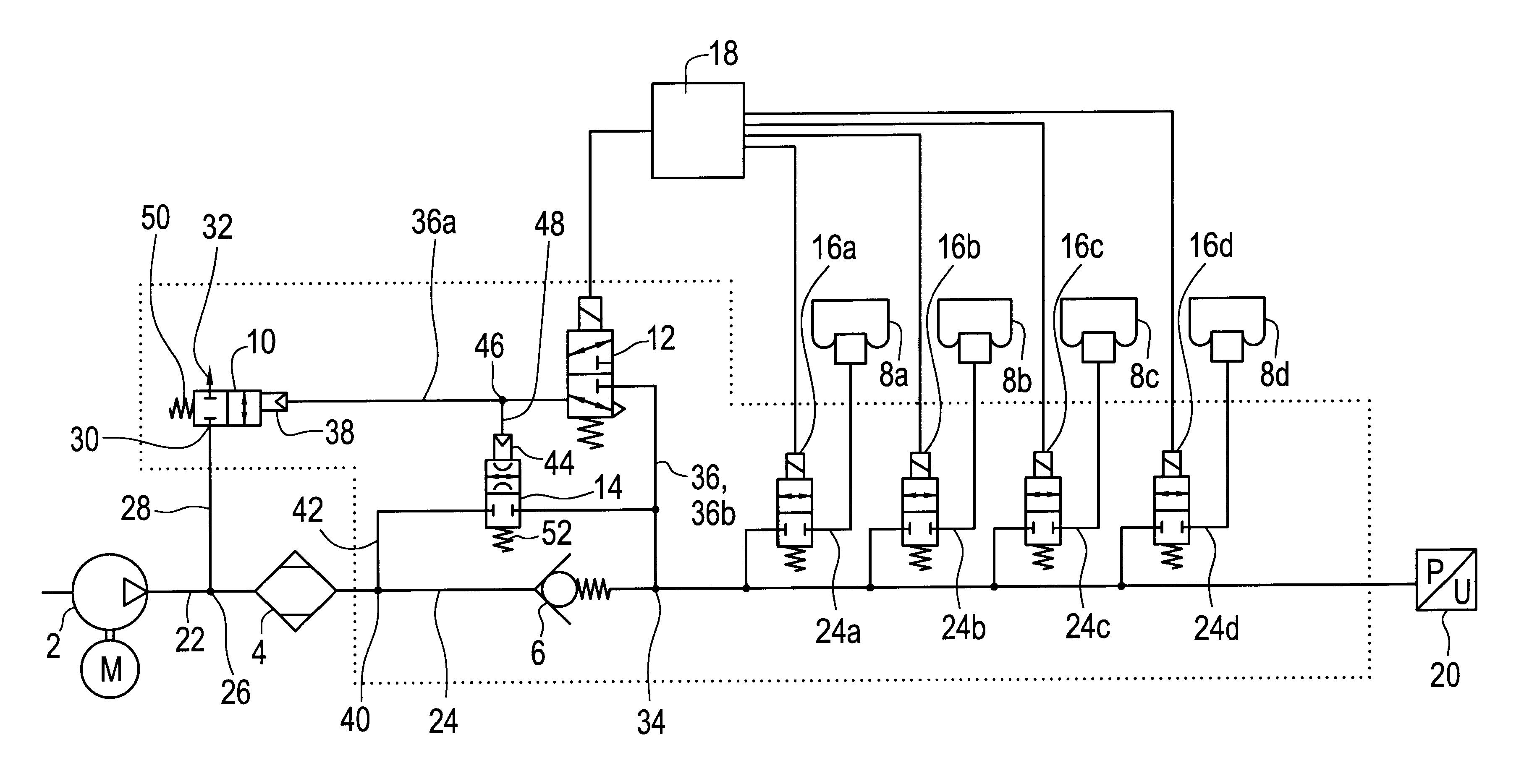
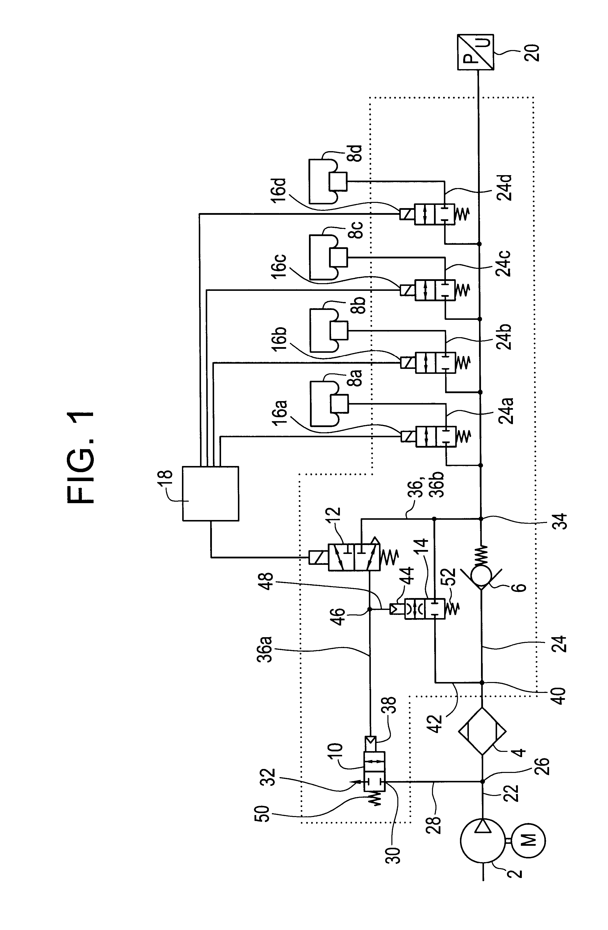
FIG. 1 shows a level adjustment device in schematic representation, wherein only the components necessary for the explanations below are shown. The level adjustment device includes a source for compressed air in the form of a compressor 2, which is connected by a pressure line 22 to the intake of an air dryer 4. On the output side, the air dryer 4 is connected by a pressure line 24 to check valve 6, and to pneumatic control input 44. Check valve 6 is connected, inter alia, to distribution valves 16a-16d, which in turn are connected to air springs 8a through 8d. A check valve 6 opening to air springs 8a through 8d is situated in pressure line 24. Past the check valve 6 (seen from the air dryer out) pressure lines 24a through 24d branch off from pressure line 24, each of which leads to one of the distribution valves 16a-16d and then lead to the air springs 8a through 8d. Each of the pressure lines 24a through 24d includes a...


PUM


Abstract

Level adjustment device for vehicles with air springs 8a through 8d, by which a vehicle body is furnished with suspension on at least one vehicle axle, which includes the following:a source of compressed air 2, which, for the purpose of filling air springs 8a through 8d, can be connected to air springs 8a through 8d via an air dryer 4, the air dryer 4, for the purpose of filling the air springs, is connected on one side to air springs 8a through 8d through a check valve 6 that is open to air springs 8a through 8d, each air spring 8a through 8d, for the purpose of emptying them, can be connected through the air dryer 4 and through a pneumatically controlled first distribution valve 10 to the atmosphere, wherein the pneumatic control input 38 of this distribution valve 10 is then impinged through a second controllable distribution valve 12 with the pressure in air springs 8a through 8d against a restoring force 50 acting on the pneumatic control input 38, the pneumatic control input 38 of the pneumatically controlled first distribution valve 10, for the purpose of ending the emptying process, can be connected to the atmosphere, wherein the air dryer 4 is connected on the other side to air springs 8a through 8d through a pneumatically controlled third distribution valve 14, wherein the pneumatic control input 44 of this distribution valve is then impinged with the pressure of air springs 8a through 8d against a restoring force 52 acting on the pneumatic control input 44.

Description

INTRODUCTION AND BACKGROUNDThe present invention relates to a level adjustment device for vehicles with a plurality of air springs, by which a vehicle body is furnished with suspension on at least one vehicle axle, which has the following characteristics:a source of compressed air, which, for the purpose of filling the air springs, can be connected to the air springs via an air dryer;the air dryer, for the purpose of filling the air springs, is connected on one side to the air, springs through a check valve that is open to the air springs;each air spring, for the purpose of emptying them, can be connected through the air dryer and through a pneumatically controlled first distribution valve to the atmosphere, wherein the pneumatic control input of his distribution valve is then impinged through a second distribution valve with the pressure in the air springs against a restoring force acting on the pneumatic control input;the pneumatic control input of the pneumatically controlled fir...

Claims


Application Information

Patent Timeline
Patent Type & Authority Patents(United States)
IPC IPC(8): B60G17/015B60G17/04B60G17/052
CPCB60G17/0155B60G17/0408B60G17/0523B60G2500/2012
Inventor BEHMENBURG, CHRISTOFWESTERKAMP, HELGE
Owner CONTINENTAL AG
Why Eureka
Try Eureka