Methods and apparatus for position determination

Inactive Publication Date: 2001-12-25
CALLAHAN CELLULAR L L C
View PDF4 Cites 29 Cited by
  • Summary
  • Abstract
  • Description
  • Claims
  • Application Information

AI Technical Summary

Benefits of technology

The object of this invention is to provide techniques, measurement and calibration methods to determine an object's position and displacement with high resolution and accuracy, better than 0.01 micrometers. This accuracy is at least one order of magnitude better than that quoted for the most accurate linear encoder in the above mentioned catalog and two orders of magnitude better than almost all of the listed encoders. Various preferred embodiments of the invention perform such determination for various object positional displacement conditions and geometries. It is noted that the accuracy of the method and apparatus of the present invention is greater (better) than the diffraction limit of the light to which the detectors are sensitive.
By averaging or otherwise processing the positional data of the light detectors, high accuracy in positional determination is obtained. Preferably, hundreds or thousands of detectors are used, resulting in improved accuracy.
The strips are preferably at an angle to the direction of motion (and to the repeat direction of the cell array) which angle is preferably chosen to optimize the number of linear detecting cells. Linear detecting cells are cells in which the boundary lines between bright and dark strips cross both sides of the detector cell which are generally perpendicular to the direction of motion. In this case the output signal from the cell is linearly related to the fraction of the cell area covered by the bright strip. In most embodiments of the invention, only "linear" cells are used in the determination of the position. Generally, the cells are rectangular and the cells are in the linear region and greater accuracy is achieved when the long sides of the detector are perpendicular to the direction of motion.
In another preferred embodiment of the invention, the illumination of the scale (which is either reflective or transparent), is done by a flashing light pulse of short duration, so as to freeze the object (if it moves) at a well-defined moment in time.
In still another preferred embodiment of the invention, means are provided for the attainment of even higher positional accuracy by improved alignment of detectors in relation to the mask strips and by use of repeated positional measurements and of averaging of the obtained positional data.

Problems solved by technology

The problems associated with this type of apparatus and this method for position determination relate principally to limitations in position determination accuracy.
Physical size, therefore limits the fine range measurements.
However, such methods are capable of less than an order of magnitude of improvement of resolution and furthermore, they do not measure the position at a point without making measurements at adjacent points.
The apparatus of FIG. 1 is also sensitive to vibrations which can lead to large errors in position determination.
He-1-22884) is, thus, not suitable for very precise, high resolution position determination.
Furthermore, such interferometers are high cost, very delicate apparatus.

Method used


Image

  • Methods and apparatus for position determination
  • Methods and apparatus for position determination
  • Methods and apparatus for position determination

Examples


Embodiment Construction

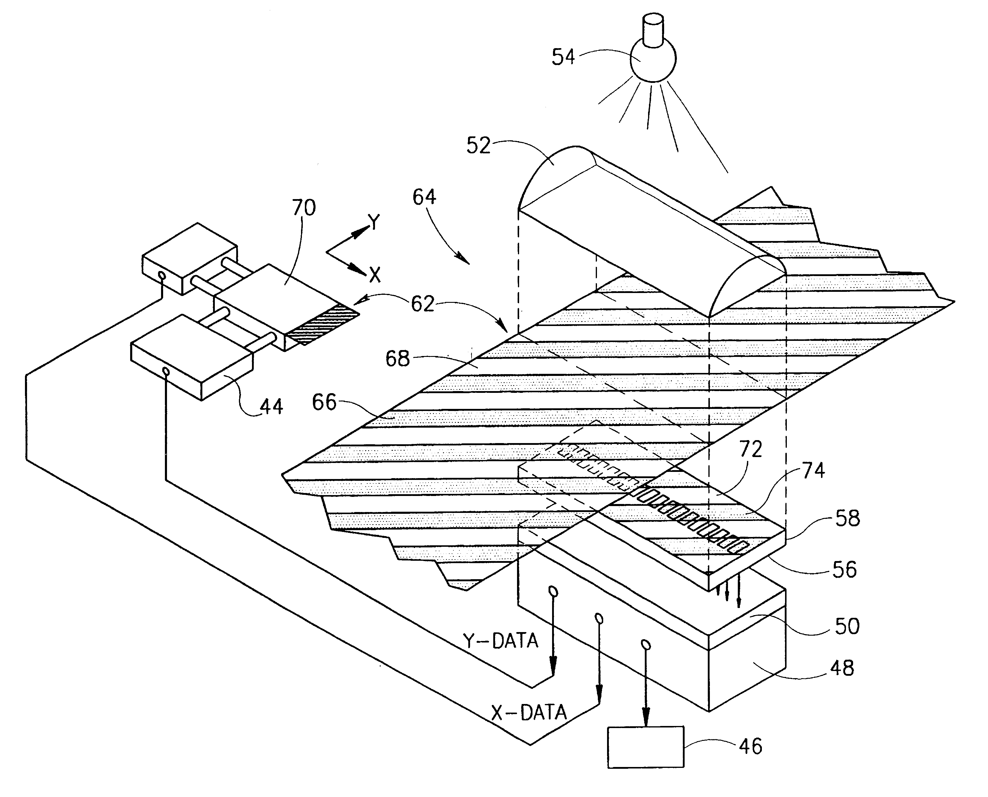
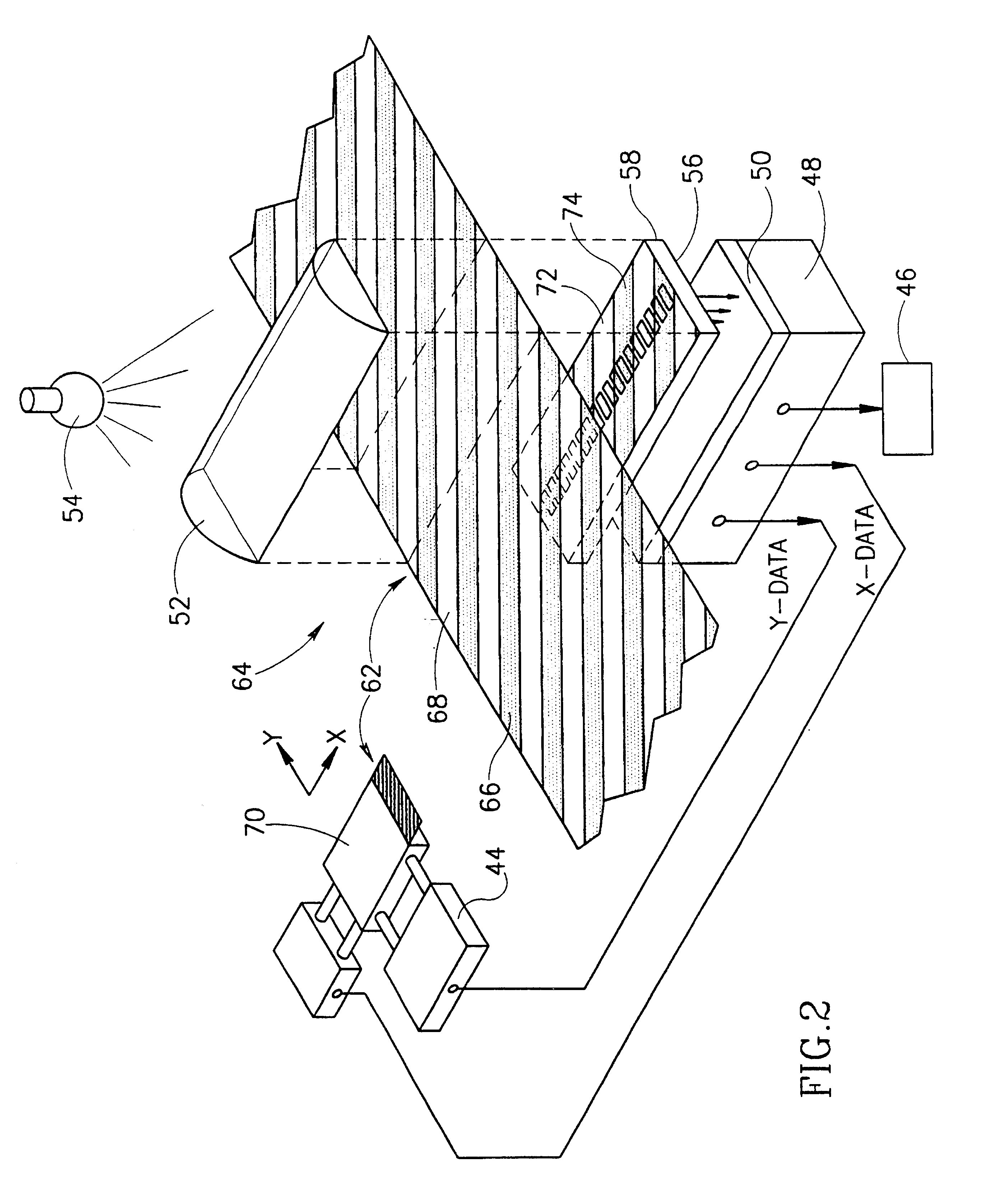
FIG. 2 illustrates an accurate position-determining apparatus 64 for determining the linear position of a movable object 70, in accordance with a preferred embodiment of the invention. Apparatus 64 utilizes a mask 62 which is mounted on object 70. The mask is comprised of parallel diagonal strips which are alternately transparent 68 and opaque 66 to light rays which originate in a lamp 54. The light rays are preferably collimated to the mask by means of a lens 52. Alternatively, a laser source can be used. The left portion of FIG. 2 shows moving object 70, having mask 62 mounted thereon. The right portion of FIG. 2 shows a greatly enlarged illustration of mask 62 together with additional apparatus associated with the mask not shown on the left portion of FIG. 2. A similar method of illustrating a complete apparatus is used in FIG. 8.

Light passing through the transparent strips in mask 62 illuminates the surface of a linear array 58 of spaced light detectors 56 (a linear array of CCD...


PUM


Abstract

Apparatus for the measurement of position of an object in a given direction, comprising: a one-dimensional array of light detectors, comprising a plurality of detectors including at least three detectors, each of which produces a signal at a given position in response to light reaching the detector; at least one edge between a dark and a light area viewed by at least one of the plurality of the detectors, which the at least one edge moves, in relation to the plurality of detectors, as the object moves in the given directions; and computing circuitry which receives signals from the at least one detector viewing the at least one edge and determines the position responsive to the signals produced by the at least one detector at the given position.

Description

RELATED APPLICATIONThis application is a US National filing of PCT Application PCT / IL97 / 00170, filed May 27,1997.FIELD OF THE INVENTIONThe present invention relates to methods and apparatus for precise position determination and in particular to a combination of electro-optical methods and apparatus and advanced data processing methods and means for the very precise determination of absolute position and incremental displacement of objects.BACKGROUND OF THE INVENTIONPrior art electro-optical apparatus for the determination of the position of a rotational objects is shown in FIG. 1. A light-opaque mask 12 having light-transparent apertures 20 is rigidly attached to and moves with an object 22, whose angular position is to be determined. Light rays emitted from a light source 10, impinge on the mask 12 and a light flux passing through the apertures in the plate is detected by a light detecting device 14, which is aligned with the mask and the source to measure the light flux.As differ...

Claims


Application Information

Patent Timeline
IPC IPC(8): G01D5/36G01D5/26
CPCG01D5/36
Inventor TALMI, AMOS
Owner CALLAHAN CELLULAR L L C
Why Eureka
Try Eureka