Pinhole video camera

a video camera and pinhole technology, applied in the field of pinhole video cameras, can solve the problems of unclear image, ineffective utilization of the entire area of the charged coupled device,

Inactive Publication Date: 2002-01-01
HARADA NOBUO
View PDF13 Cites 31 Cited by
  • Summary
  • Abstract
  • Description
  • Claims
  • Application Information

AI Technical Summary

Problems solved by technology

However, in the above-mentioned conventional pinhole video camera, overall area of the charged coupled device can not effectively be utilized due to fisheye characteristics of a lens disposed between the fixed charged coupled device and the pinhole.
As a result, with the conventional pinhole camera, it is impossible to take pictures because of low luminance, and there is a problem that it is impossible to adjust focus of a subject in an range from a point closely adjacent to the camera to a point far from the camera, resulting in unclear image.

Method used


Image

  • Pinhole video camera
  • Pinhole video camera
  • Pinhole video camera

Examples


Embodiment Construction

Embodiments of the present invention will be explained with reference to drawings.

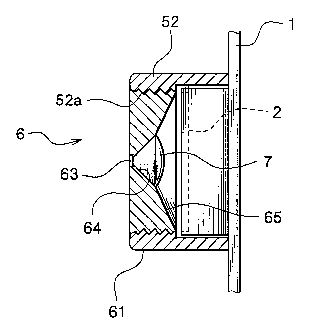
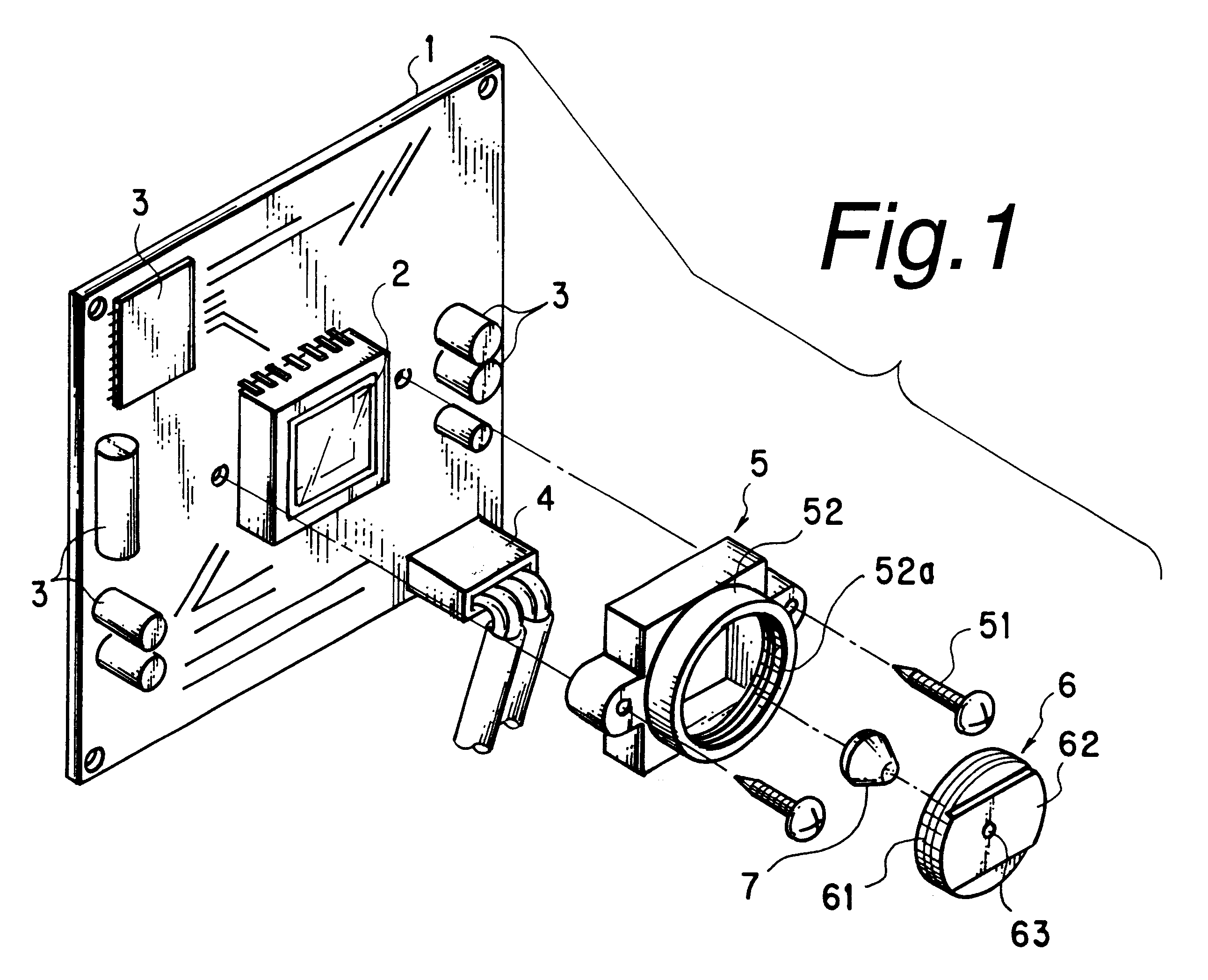
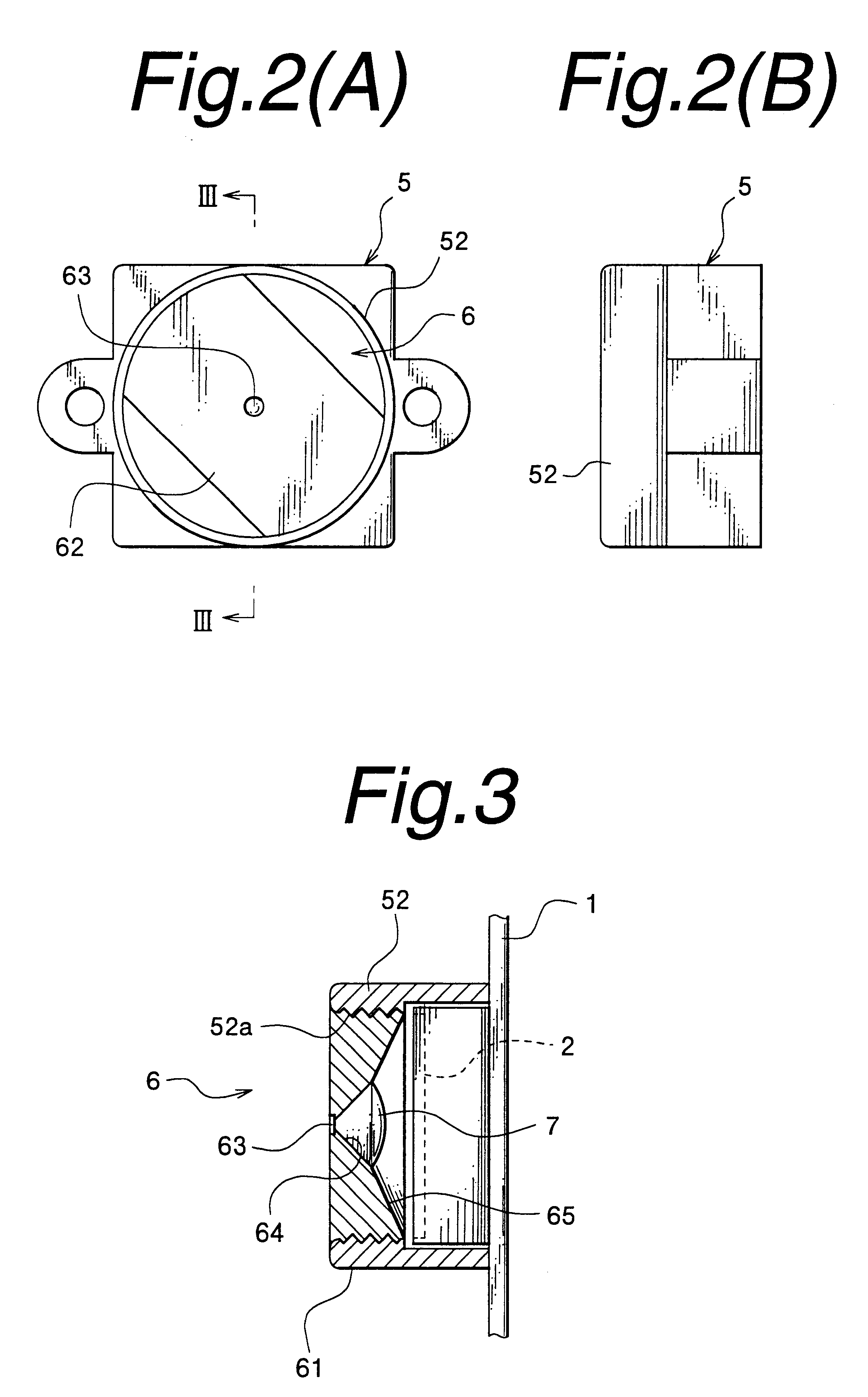
FIG. 1 is an exploded perspective view of a pinhole video camera according to an embodiment of the present invention, in which reference numeral 1 shows a printed circuit board, 2 a fixed charged coupled device (hereinafter referred to as "CCD"), 3 memory means for storing a single frame image which is generated by image signal from the CCD 2 and an electronic part constituting signal converting means and the like as a known circuit for displaying the frame image to a displayer. Numeral 4 is a connector with wires to connect the aforementioned circuits to power source and the displayer.

Numeral 5 shows a holder which is formed to cover overall upper surface of the CCD 2 and is secured to the printed circuit board 1 through screws 51. On the front surface of the holder 5 is formed a cylindrical portion 52 and on the inner wall of the cylindrical portion 52 is formed a female screw portion 52a.

Numeral 6 s...


PUM


Abstract

A pinhole camera in which a conical lens with an apical angle of 91.13° to 91.15° is used to correct the fisheye characteristics, and ⅓-inch fixed charged coupled device and a pinhole with a diameter of 0.8 mm are adopted to obtain clear image of a subject in an range from a point closely adjacent to the camera to a point far from the camera with strong contrast. The pinhole video camera comprising: a printed circuit board to which ⅓-inch fixed coupled charged device is attached; a holder fixed so as to cover a front surface of the coupled charged device of the printed circuit board; a lens holder having a pinhole with a diameter of 0.8 mm; a conical convex lens with an apical angle of 91.13° to 91.15°, the conical convex lens fixed on a rear face side of the pinhole of the lens holder.

Description

1. Field of the InventionThe present invention relates a pinhole video camera as a non-focus video camera.2. Description of the Related ArtGenerally, a pinhole video camera, which changes, without focusing, image of a subject in an range from a point closely adjacent to the camera to a point far from the camera into electrical signals, utilizes 1 / 4-inch fixed charged coupled device.However, in the above-mentioned conventional pinhole video camera, overall area of the charged coupled device can not effectively be utilized due to fisheye characteristics of a lens disposed between the fixed charged coupled device and the pinhole. As a result, with the conventional pinhole camera, it is impossible to take pictures because of low luminance, and there is a problem that it is impossible to adjust focus of a subject in an range from a point closely adjacent to the camera to a point far from the camera, resulting in unclear image.The present invention has been made in consideration of the ab...

Claims


Application Information

Patent Timeline
Patent Type & Authority Patents(United States)
IPC IPC(8): H04N5/225G03B19/16
CPCH04N5/2254H04N5/2251H04N23/55H04N23/50
Inventor HARADA, NOBUO
Owner HARADA NOBUO
Why Eureka
Try Eureka