Swimming pool directional wireless signal trigger based on RFID technology

A wireless signal and trigger technology, applied in signal transmission systems, instruments, image communication, etc., can solve problems such as increased stress and fatigue of lifeguards, panic on the spot, inaccurate position judgment, etc., to overcome the influence of the environment and people , Reduce fatigue and tension, relieve fatigue and tension

Active Publication Date: 2015-10-21
马科峰
View PDF10 Cites 10 Cited by
  • Summary
  • Abstract
  • Description
  • Claims
  • Application Information

AI Technical Summary

Problems solved by technology

[0004] 1. Not suitable for densely populated waters: For example, the design of using underwater infrared detection and judging the static time of obstructions is not suitable for crowded waters, and is not suitable for synchronous and integrated intelligent supervision of a large number of people;
[0005] 2. High false alarm rate: Due to the problem of the alarm algorithm, the false alarm rate of the SOS alarm signal is high, causing panic and disharmony on the scene, which invisibly increases the pressure and fatigue of lifeguards
Moreover, the physical reaction mechanism when an SOS event occurs is too primitive and monotonous, and cannot be detected and dealt with effectively in a timely manner;
[0006] 3. The alarm prompt is not clear and is subject to real-time networking with the network PC server: most of the current existing technologies use video surveillance or swimming stroke image comparison algorithms. Perform data collection and definition of individual swimmers
Moreover, the implementation of the image acquisition and comparison and calculation results is more complicated and must be realized by relying on real-time onli...

Method used


Image

  • Swimming pool directional wireless signal trigger based on RFID technology
  • Swimming pool directional wireless signal trigger based on RFID technology
  • Swimming pool directional wireless signal trigger based on RFID technology

Examples


Embodiment Construction

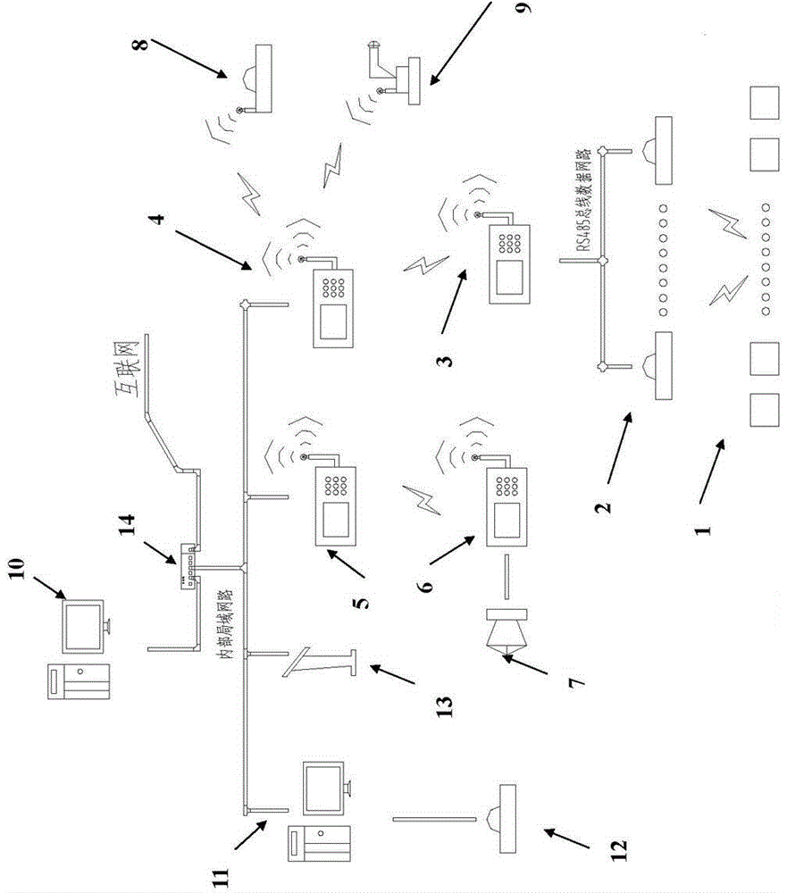
[0033] The present invention proposes a swimming pool directional wireless signal trigger based on RFID technology. Several directional wireless signal triggers 2 installed at the bottom of the swimming pool can receive the event ID generated by the RFID electronic tag 1. Each directional wireless signal trigger 2 has a unique Transceiver ID, the transceiver ID includes address code, LED event indicator light, miniature pinhole camera.

[0034] The address code determines that the swimmer is in the fixed coordinate position of the swimming pool through logical calculation, and at the same time, when the directional wireless signal trigger 2 is activated, the miniature pinhole camera inside is installed for real-time image monitoring of its local field area.

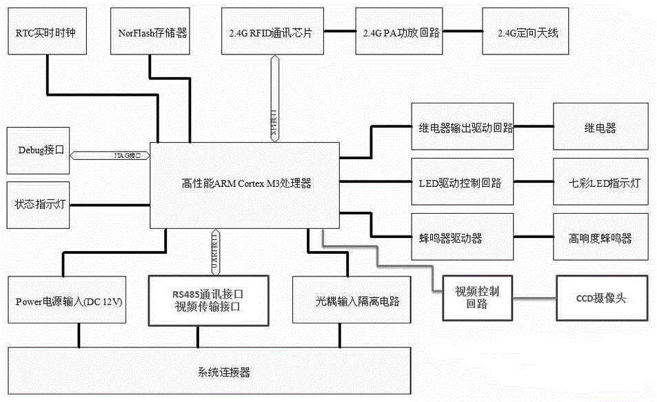
[0035]Directional wireless signal trigger 2 includes MCU (CPU) central processing chip, drive power control circuit, relay input control circuit, battery signal input and output circuit, LED colorful light-emitting diode, ...


PUM


Abstract

The invention discloses a swimming pool directional radio signal trigger based on an RFID (Radio Frequency Identification) technology. The directional radio signal trigger comprises a unique transceiver ID, an LED (Light Emitting Diode) event indicator lamp and a miniature pinhole camera, wherein the transceiver ID contains address codes; the address codes are used for determining a fixed coordinate position of a swimmer in the swimming pool through logical computing, meanwhile, when the directional radio signal trigger is activated, the miniature pinhole camera mounted therein monitors and photographs images of a local site area of the directional radio signal trigger in real time. The swimming pool directional wireless signal trigger based on the RFID technology, provided by the invention, is applied in a drowning prevention safety guarantee system based on the RFID technology, can be used for monitoring water bottom state of the swimming pool in an event area through a shore-side monitoring system, and can learn real-time state image information.

Description

technical field [0001] The invention relates to the technical field of safety assurance, and more specifically, relates to a swimming pool directional wireless signal trigger based on RFID technology. Background technique [0002] Swimming is both a traditional and a popular sport that is practiced in various forms every year by both adults and children. In recent years, child drowning incidents in swimming pools have continued to occur. As far as Shanghai is concerned, there have been many child drowning incidents in some more formal swimming pools in recent years. This not only brings great grief to the family, but also poses a business risk to the business unit. How to ensure children's swimming safety and how to strengthen the protection mechanism of swimming pools is a common hot topic in society. [0003] The current overall solution and technology have the following core problems: [0004] 1. Not suitable for densely populated waters: For example, the design of usin...

Claims


Application Information

Patent Timeline
IPC IPC(8): H04N5/232G08C17/02
Inventor 马科峰
Owner 马科峰
Why Eureka
Try Eureka