X-ray pinhole camera for intense laser light condition and installation and adjustment method

A pinhole camera and X-ray technology, which is applied in optics, instruments, photography, etc., can solve problems such as X-ray pinhole camera failure, and achieve the effects of saving adjustment time, increasing accuracy, and improving signal-to-noise ratio

Active Publication Date: 2016-07-27
中国工程物理研究院上海激光等离子体研究所
View PDF5 Cites 10 Cited by
  • Summary
  • Abstract
  • Description
  • Claims
  • Application Information

AI Technical Summary

Problems solved by technology

When the high-energy g-rays are strong enough and the background noise is large enough, the pinhole

Method used


Image

  • X-ray pinhole camera for intense laser light condition and installation and adjustment method
  • X-ray pinhole camera for intense laser light condition and installation and adjustment method
  • X-ray pinhole camera for intense laser light condition and installation and adjustment method

Examples


Embodiment 1

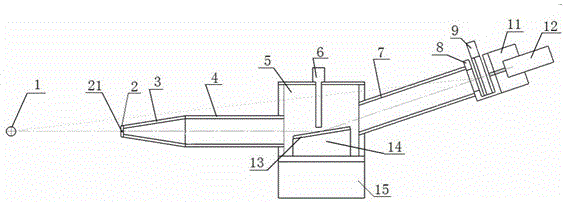
[0034] Such as image 3 , Figure 4 with Figure 5 As shown, this embodiment is used for an X-ray pinhole camera under strong laser conditions, and the pinhole camera includes a pinhole plate 2, a pinhole seat housing 3, a front light tube 4, a grazing incidence mirror chamber, and a rear light tube 7. Film chamber 8, film cassette 9, filter frame 10, filter disc 10-1, negative film 10-2, two-dimensional adjustment laser seat 11, semiconductor laser 12 and two-dimensional adjustment frame 15, in the film chamber 8 A two-dimensional adjustment laser seat 11 is fixedly arranged on the outside, and a semiconductor laser 12 is installed on the side corresponding to the film chamber 8 on the two-dimensional adjustment laser seat 11. A through hole for adjusting the passage of the laser light; the grazing incidence mirror chamber includes a mirror chamber housing 5, a light blocking lead plate 6, a grazing incidence mirror 13 and a two-dimensional adjustment grazing incidence mirr...

Embodiment 2

[0047] Such as image 3 , Figure 4 with Figure 5 As shown, the present embodiment is used for an X-ray pinhole camera under strong laser conditions. In order to realize high-temperature plasma X-ray imaging under strong laser irradiation and high background noise conditions, the pinhole camera includes a pinhole plate 2, a pinhole Housing housing 3, front light tube 4, grazing incidence mirror room, rear light tube 7, film chamber 8, film box 9, filter frame 10, filter 10-1, film 10-2, two-dimensional adjustment laser Seat 11, semiconductor laser 12 and two-dimensional adjustment frame 15, two-dimensional adjustment laser seat 11 is fixedly arranged on the outside of described film chamber 8, semiconductor laser is installed on the side corresponding to film chamber 8 on two-dimensional adjustment laser seat 11 12. At the optical axis positions of the two-dimensional adjustment laser seat 11 and the film chamber 8, there are through holes for the adjustment laser to pass t...


PUM

PropertyMeasurementUnit
Thicknessaaaaaaaaaa
Sizeaaaaaaaaaa
Lengthaaaaaaaaaa

Abstract

The invention relates to an X-ray pinhole camera for an intense laser light condition. The pinhole camera comprises a pinhole plate, a pinhole base housing, a front light-passing barrel, a grazing incidence mirror room, a back light-passing barrel, a negative film room, a negative film box, a filter disc frame, a filter disc, a negative film, a two-dimensional adjusting laser base, a semiconductor laser device and a two-dimensional adjusting bracket, wherein the two-dimensional adjusting laser base is fixedly arranged at the outer side of the negative film room; the semiconductor laser device is arranged at one side, corresponding to the negative film room, of the two-dimensional adjusting laser base; and through holes through which an adjusting laser light passes are formed in optical axis positions of the two-dimensional adjusting laser base and the negative film room. The influence of an ultra-intense g ray under the intense laser light condition is effectively eliminated; the X-ray pinhole camera is well applied to high-temperature dense plasma imaging under the intense laser light condition; and quick and stable installation and adjustment on the X-ray pinhole camera can be carried out through a laser-assisted targeting method.

Description

technical field [0001] The invention relates to the field of imaging, in particular to an X-ray pinhole camera and an installation and adjustment method used under strong laser conditions, and is a high-temperature plasma X-ray imaging camera that can be used under conditions of strong laser irradiation and high background noise. Grazing incidence X-ray pinhole camera. Background technique [0002] X-ray pinhole camera is one of the important diagnostic equipment in high-temperature plasma imaging diagnosis, and is widely used in various researches related to high-temperature dense laser plasma. The X-ray pinhole camera can obtain information such as the shape of the laser focal spot, temperature distribution, size, and contour by self-illuminating imaging of the plasma to be measured, which is of great significance for qualitatively understanding the state of the laser focus and the state of the plasma. [0003] The traditional X-ray pinhole camera is based on the principl...

Claims


Application Information

Patent Timeline
IPC IPC(8): G03B42/02
CPCG03B42/025
Inventor 王琛安红海熊俊方智恒王伟孙今人王轶文张众
Owner 中国工程物理研究院上海激光等离子体研究所
Why Eureka
Try Eureka