Casing structure of communication equipment

a technology of communication equipment and casing, which is applied in the direction of casing/cabinet/drawer details, electrical apparatus casings/cabinets/drawers, coupling device connections, etc., can solve the problems of heavy weight, risk of failure to fall down, and the electrical components mounted on the panel in the casing suffer maloperation, so as to facilitate handling and improve operability and operation convenience.

Inactive Publication Date: 2002-01-08
NEC CORP
View PDF7 Cites 15 Cited by
  • Summary
  • Abstract
  • Description
  • Claims
  • Application Information

AI Technical Summary

Benefits of technology

In view of the above depicted status of the art, it is an object of the present invention to provide a casing structure for a communication equipment in which panels mounted in the inside of the communication equipment and the messenger wire in the mounted state of the casing to the messenger wire are electrically insulated from each other for prohibiting impediments otherwise caused by the extraneous noise current and in which the mounting portion is of a handle structure for facilitated transport for assuring facilitated handling and for improving operability and operating convenience.

Problems solved by technology

The first problem is that electronic components mounted on a panel in a casing suffers maloperations by the extraneous noise transmitted over the messenger wire and is destroyed in the worst case.
The second problem is that the equipment of this sort is heavy in weight and difficult to transport in the stage of production in the factory or in the mounting stage on the mounting site such that there is risk of a failure to fall down.

Method used


Image

  • Casing structure of communication equipment
  • Casing structure of communication equipment
  • Casing structure of communication equipment

Examples


examples

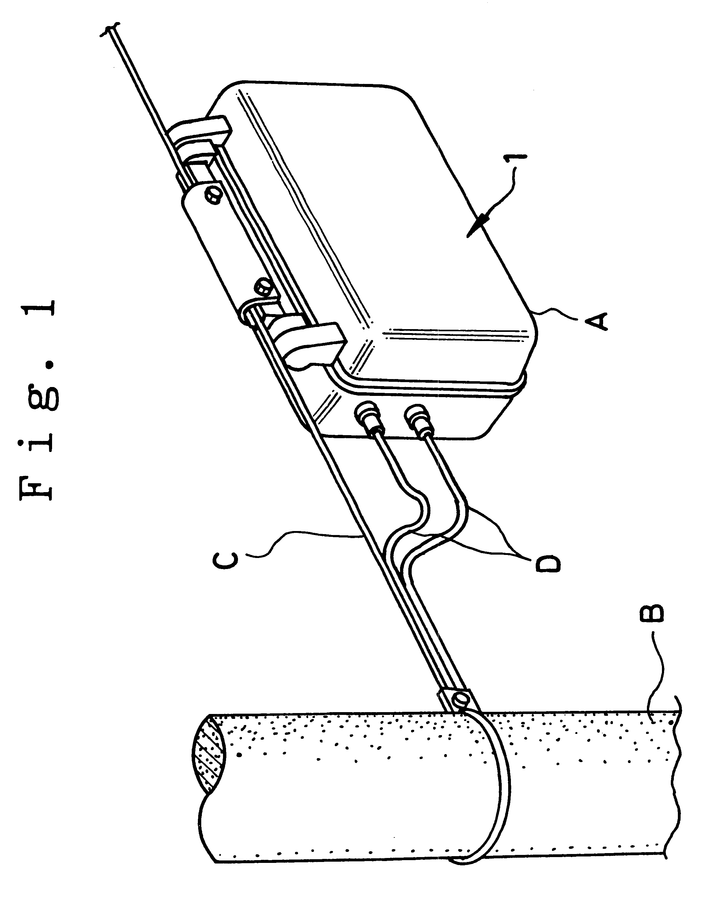
An example of the present invention is explained for more detailed illustration of the preferred embodiment of the invention. The mounting site of the communication equipment A used in a simplified portable telephone system is determined by optimum base stations designated for presenting telephone services to pedestrians on a road. As one of the mounting sites, the messenger wire C installed between telegraph poles B is preferentially used. The messenger wire C is formed by twisted stainless steel wires and installed along with other communication cables, such as those for CATV.

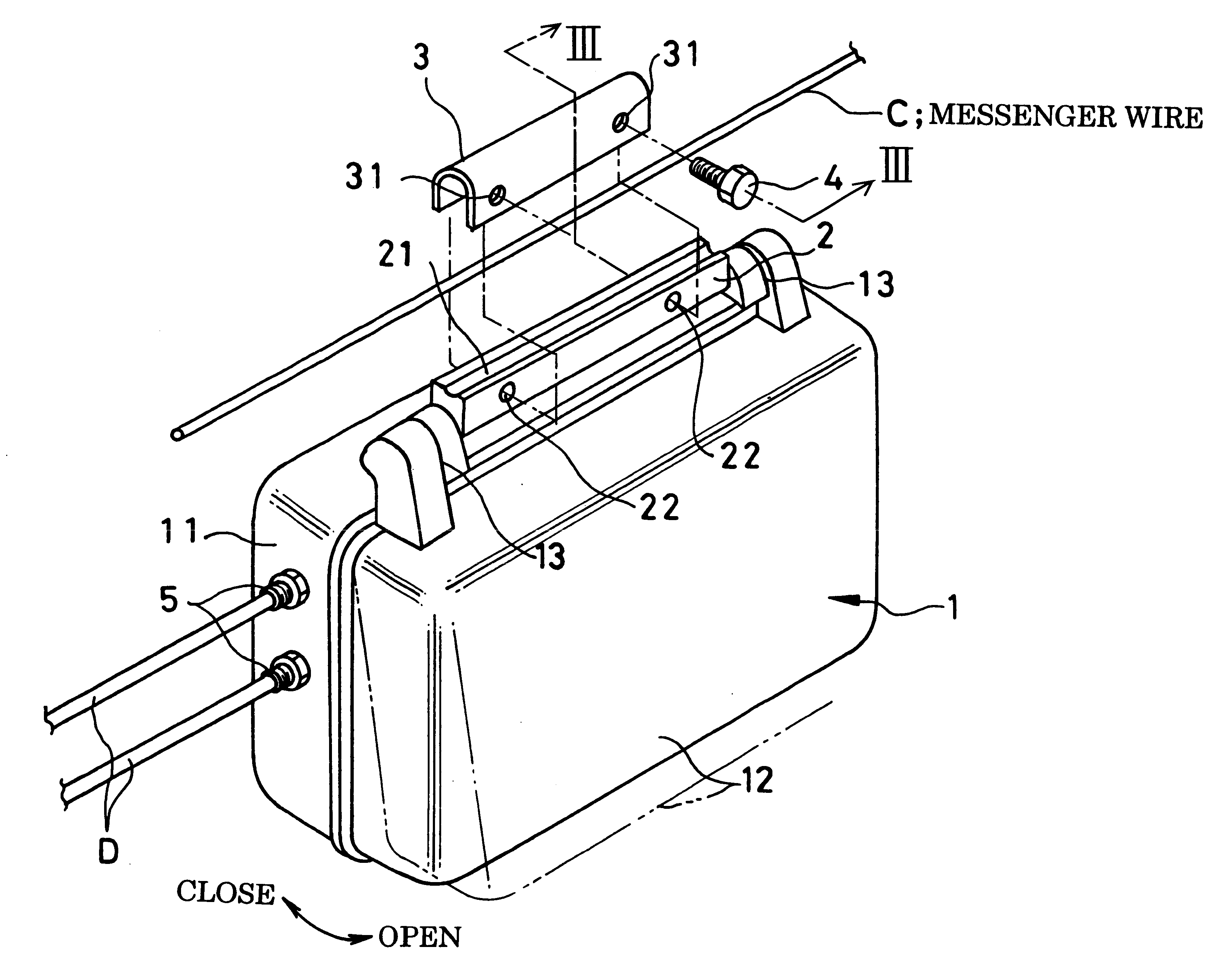
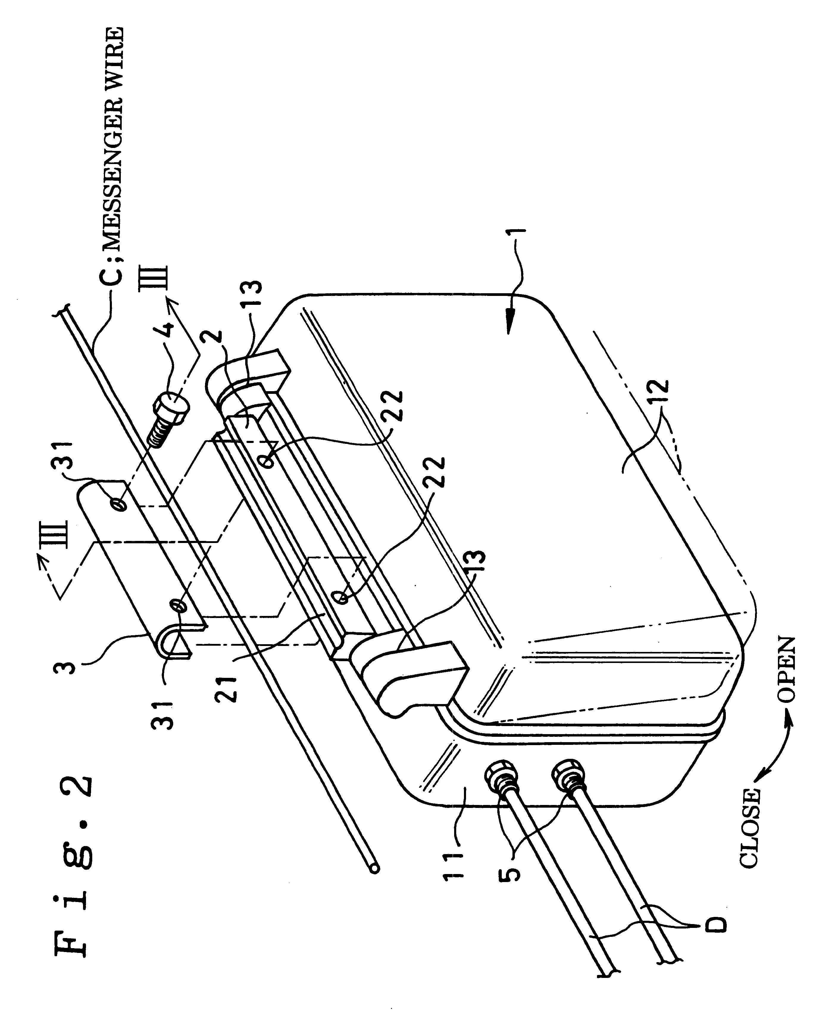
FIG. 2 is an exploded perspective view showing an embodiment of the present invention. The casing 1 of a communication equipment A is fabricated by aluminum die-casting and is roughly made up of the casing portion 11 and the cover 12. The casing 1 carries a connection plug 5 for connection to outside and has housed therein panels such as printed circuit boards carrying electrical or electronic components ther...


PUM


Abstract

A casing structure for a communication equipment in which panels mounted in the casing are electrically insulated from a messenger wire. When the casing of the communication equipment is mounted on the messenger wire, the insulation prohibits impediments otherwise caused by extraneous noise current flowing in the messenger wire. The mounting portion of the case has a handle structure which provides improved operability and convenience.

Description

This invention relates to a casing structure of a communication equipment used for a wireless communication base station for e.g., the personal handy phone system (PHS). More particularly, it relates to a casing structure having a suspension structure from a messenger wire installed between communication pillars as one of the mounting sites and which is improved in workability during transport and installation.As a prior art of this sort, the JP Utility Model Kokai JP-Utility Model Kokai-A-2-62103 proposes, a fastener device between an equipment casing and a messenger wire having a grooved hooked member having a unitary structure with the equipment casing, a U-shaped clamping member and a tightening member, such as a bolt, for thrusting the inner rim portion of a web of the clamping member against the end face of the hooked member for securing the clamping member. The clamping member has the inner peripheral side of a web of the U-shape thereof abutted against the end face of the U-...

Claims


Application Information

Patent Timeline
Patent Type & Authority Patents(United States)
IPC IPC(8): H02G7/00H02G15/10H02G7/14H02G15/117H05K5/02H04B7/26H04Q1/02
CPCH02G7/14H05K5/0204H02G15/117
Inventor OYAMADA, TAKASHI
Owner NEC CORP
Why Eureka
Try Eureka