A-scan ISAR classification system and method therefor

a classification system and radar technology, applied in the field of radar system and radar signature identification methods, can solve the problems of large antennas not being used, isar systems not being able to produce profile images of targets, and complicated profile image developmen

Inactive Publication Date: 2002-01-08
LOCKHEED MARTIN CORP
View PDF10 Cites 75 Cited by
  • Summary
  • Abstract
  • Description
  • Claims
  • Application Information

AI Technical Summary

Problems solved by technology

However, in many instances, a large antenna cannot be used due to the physical constraints of the radar platform.
However, the ISARs use the motion of the target to synthesize a large aperture antenna and not the motion of the radar platform itself.
While such systems have been quite successful in presenting images to trained personnel for interpretation, several major drawbacks have been encountered.
Specifically, while rotational target motion need not be large for acceptable results to be obtained (i.e. about 1.degree. of pitching motion is often sufficient), ISAR systems cannot produce a profile image if the target is stationary.
Further, accuracy of the profile image development is also complicated and errors occasioned by other motions of the target such as roll and yaw.
Therefore, the ISAR systems cannot be calibrated to provide any form of standardization of the profile images produced.
As can be understood, the processing of the image is thus very computationally intensive and relatively slow in providing a response.
Unfortunately, this recognition skill is not trivial and a human operator must learn how to recognize distinct classes of ships in an ISAR image, requiring long training times. Typical training courses consist of an intensive course of several weeks duration to learn features of an ISAR image on which a classification may be based.
Further, this recognition skill is easily lost because of the subtleties of differences of ISAR images and must be constantly reinforced and refreshed in order for the operator to retain such recognition skills.
Thus, both data acquisition and database management present substantial difficulty in addition to data processing requirements.
Currently, there are no off-the-shelf mission computers with the processing capability to provide reasonably accurate classification in substantially real time.
Consequently, available resources, in current off-the-shelf mission computers, fall far short of what is necessary to arrive at satisfactory recognition results.

Method used


Image

  • A-scan ISAR classification system and method therefor
  • A-scan ISAR classification system and method therefor
  • A-scan ISAR classification system and method therefor

Examples


Embodiment Construction

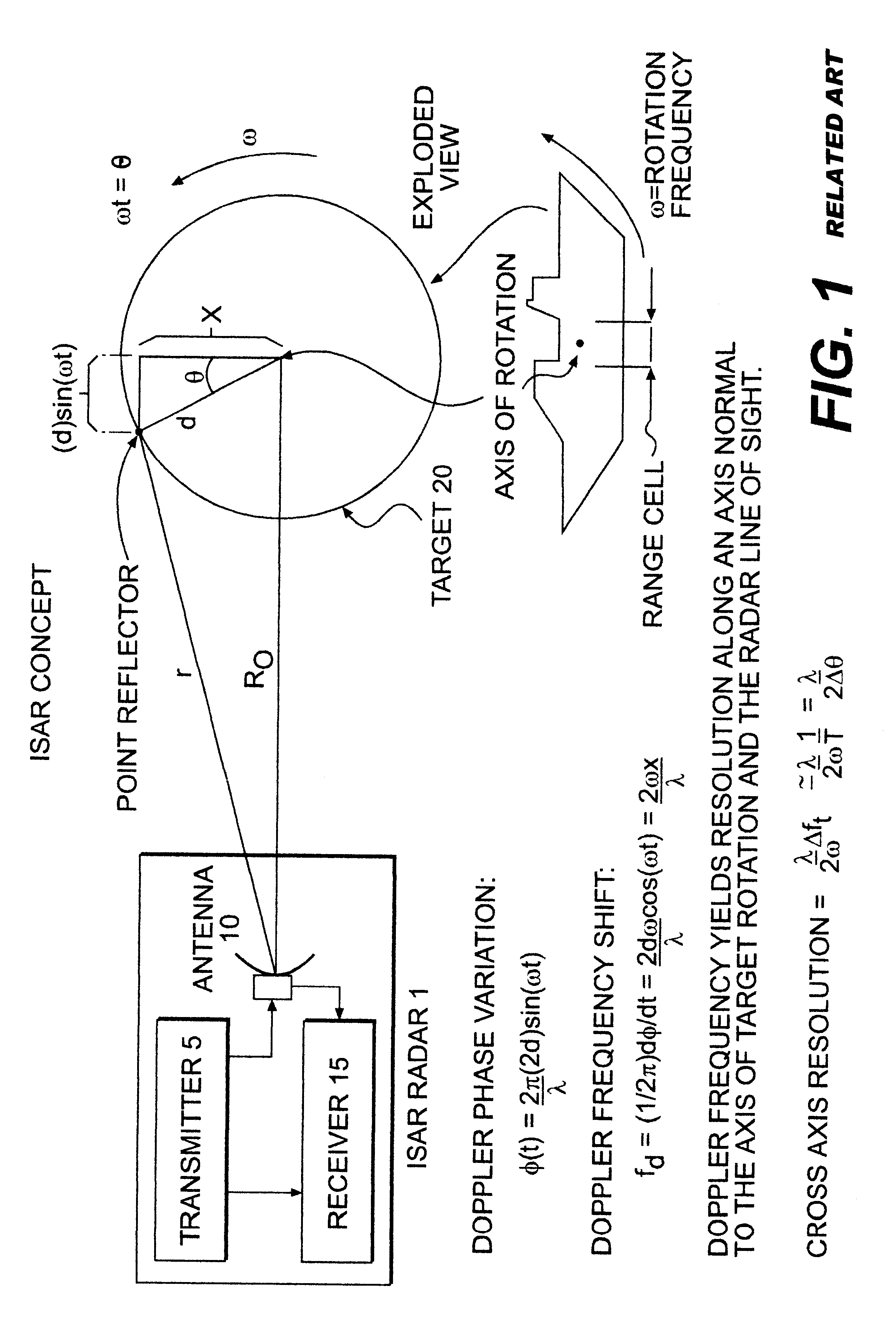
Referring now to the drawings and, more particularly to FIG. 1, there is illustrated, in highly schematic form, the basic environment of an inverse synthetic aperture radar system. All radar systems 1 basically include a transmitter 5 for generating an electromagnetic wave, and an antenna for radiation and receipt of the electromagnetic wave reflected by the target, and a receiver 15 for receiving the antenna collected energy and processing the same in a selective manner. It is, of course, preferred that the receiver 15 preserve as much information as possible that may be included in the reflected energy so as to accurately image the target 20.

Still referring to FIG. 1, the target 20 is depicted as a seaborne vessel such that the natural motion of the vessel such as, for example, pitching about an assumed center of rotation due to encountering waves, causes differences in relative motion of portions of the vessel. Thus, structural features farther from the center of rotation (e.g. h...


PUM


Abstract

A target recognition system and method wherein only target amplitude data, i.e., coherent A-scan data, is interrogated for target recognition. Target aspect angle is ignored within the angular segmentation of the feature library without degrading classification performance. Observed signature characteristics are collected at various aspect angles and through unknown and arbitrary roll, pitch and yaw motions of each anticipated target and provided to a neural network as training sets. The neural network forms feature vectors for each target class which are useful for valid classification comparisons in all sea states, especially in calm and littoral waters. These feature vectors are useful for valid classification comparisons over at least 30 degrees of target aspect angle.

Description

1. Field of the InventionThe present invention generally relates to radar systems and radar signature identification methods and, more particularly, to methods and systems for automatically classifying targets imaged on Inverse Synthetic Aperture Radar systems.2. Background DescriptionSynthetic Aperture Radars (SARs) produce a two-dimensional (2-D) image (with intensity as a pseudo non-spatial third image dimension) where one dimension in the image is a range and the other dimension is an azimuth (or cross range). Range is a measure of the "line-of-sight" distance from the radar to the target and is determined by measuring the time between the transmission of a radar signal to the receipt of the reflected signal (e.g., echo) from a target. The range resolution may be limited by the transmitted pulse width so that, for example, a narrow pulse width may be required to yield fine range resolution.In order to produce a relatively fine azimuth resolution, a large antenna is needed to foc...

Claims


Application Information

Patent Timeline
Patent Type & Authority Patents(United States)
IPC IPC(8): G01S7/02G01S7/41G06K9/32G01S13/00G01S13/90
CPCG01S7/412G06K9/3241G01S2013/9064G01S7/417G01S13/9064G01S13/9027G06V10/255
Inventor RICHARDSON, DENNIS W.RYAN, PATRICK S.
Owner LOCKHEED MARTIN CORP
Why Eureka
Try Eureka