
Pallet changer apparatus

a technology of pallet changer and rotary plate, which is applied in the direction of work transfer apparatus, furniture, charge manipulation, etc., can solve the problems of affecting the reliability of the operation, and affecting the operation of the operator

Inactive Publication Date: 2002-01-29
BROTHER KOGYO KK
View PDF5 Cites 7 Cited by
  • Summary
  • Abstract
  • Description
  • Claims
  • Application Information

AI Technical Summary

Benefits of technology

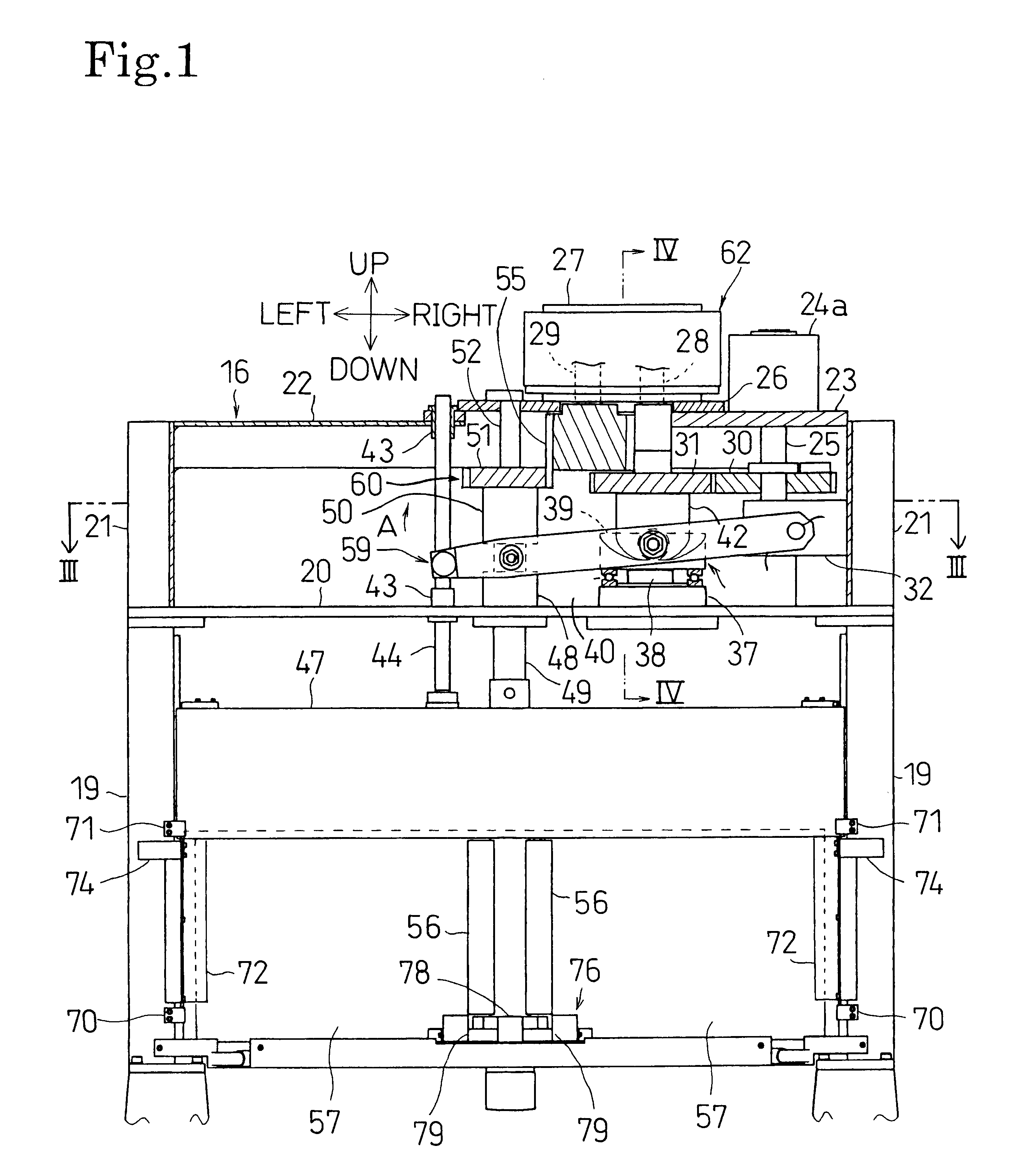
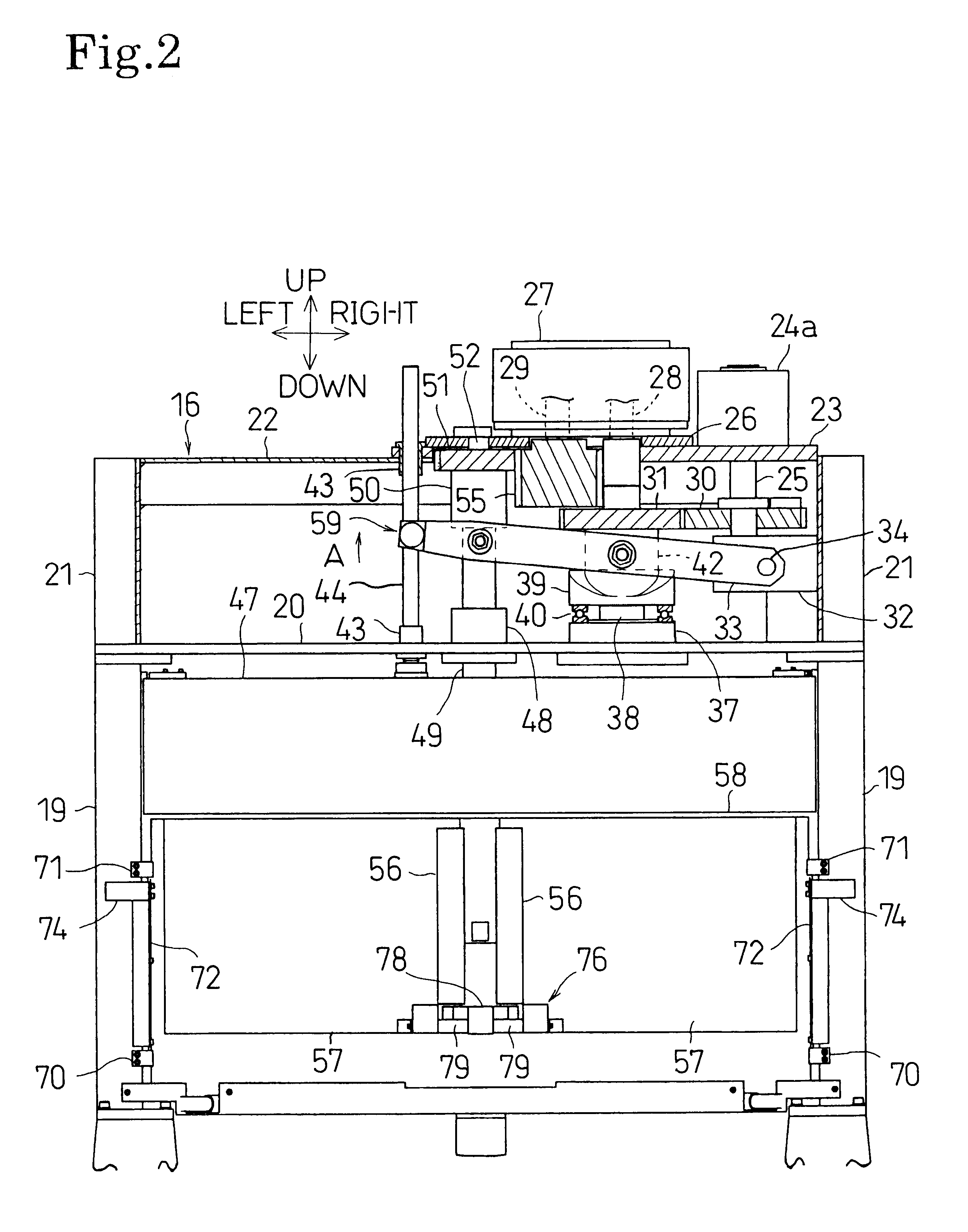
In the above-described pallet changer apparatus, the pallet changing arm is moved up and down and turned by using the single drive force source provided above the table. Due to this structure, the table can be reduced in size so as to allow an operator to perform operations without being impeded by the table. The structure also eliminates the need to determine the drive times of a plurality of drive sources based on output signals of sensors, thereby decreasing the possibility of a malfunction and improving reliability. Also, because the motor is disposed above the table, it is convenient to access to perform maintenance on the motor.
Since the drive time of the turning mechanism and the drive time of the raising / lowering mechanism are set by the first cam drive portion and the second can drive portion, the pallet changing arm is turned and raised and lowered reliably at the set timings without malfunctioning. Therefore, the reliability of the apparatus further improves.
The provision of the partition cover prevents an undesired event such as, for example, during the processing of a workpiece, processing debris traveling from the processing position to the setup position. Furthermore, since it is unnecessary to provide dedicated drive force sources to turn and raise and lower the partition cover, the apparatus structure can be simplified.

Problems solved by technology

Therefore, the entire size of the table is large so that the table impedes an operator from performing operations smoothly.
Also, because the motor is disposed below the table, it is difficult to access to perform maintenance on the motor.
Furthermore, since the drive times of the cylinder and the motor needs to be determined based on output signals of sensors, there exists a rather high possibility of a malfunction, thereby resulting in decreased reliability.

Method used


Image

  • Pallet changer apparatus
  • Pallet changer apparatus
  • Pallet changer apparatus

Examples


Embodiment Construction

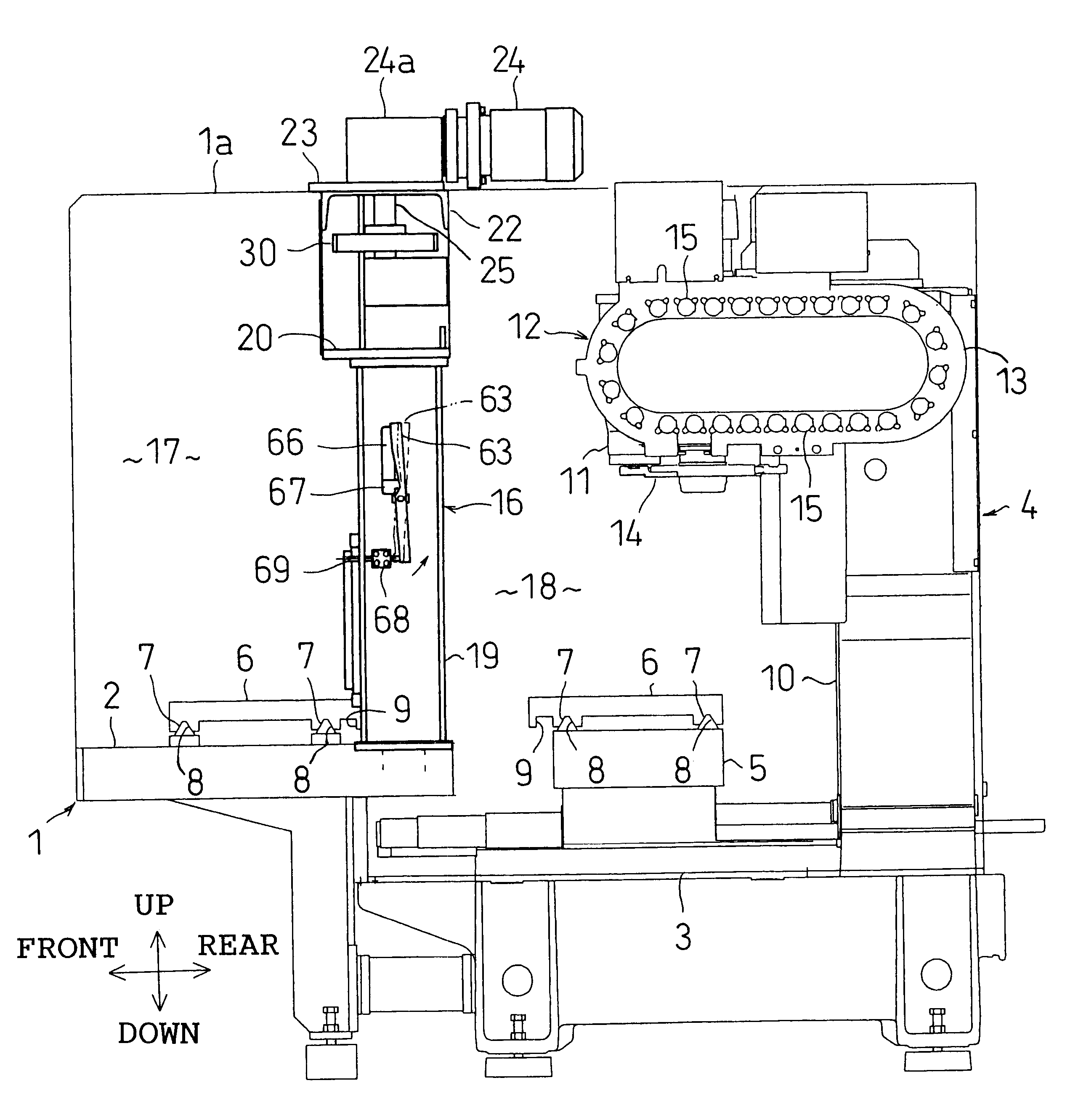
A preferred embodiment of the present invention will be described in detail hereinafter with reference to the accompanying drawings. Referring to FIG. 9, a table 1, placed on a surface, such as a floor in a factory, is covered with a splash cover 1a. The table 1 has a higher table portion 2 and a lower table portion 3 that are provided forward and rearward, respectively, in the table 1. A machining center 4 is mounted on the rearward lower table portion 3. The machining center 4, that is, a machine tool, is constructed as described below.

MACHINING CENTER 4

A work table 5 is mounted on an upper surface of the lower table portion 3 in such a manner that the work table 5 is movable rightward, leftward, forward, and rearward. A pallet 6 is placed on an upper surface of the work table 5. A workpiece (not shown) is placed on an upper surface of the pallet 6. The work table 5 has a plurality of triangular-shaped positioning protrusions 7. The pallet 6 has a plurality of triangular-shaped po...


PUM

PropertyMeasurementUnit
Forceaaaaaaaaaa
Sizeaaaaaaaaaa

Abstract

In a pallet changer apparatus, a pallet changing arm is connected to a motor via a raising / lowering mechanism and an intermittent drive unit. During operation of the motor, the pallet changing arm is raised from a lowermost position to an uppermost position, and is held at the uppermost position, and then is lowered from the uppermost position to the lowermost position. The pallet changing arm is also connected to the motor via a turning mechanism and a second cam drive portion. During operation of the motor, the pallet changing arm is turned while being held at the uppermost position. The pallet changing arm is moved up and down and turned by using the single motor provided above a table. The table below the pallet changing arm is reduced in size so as to allow an operator to perform operations without being impeded by the table. The structure also eliminates the need to determine the drive time of a plurality of drive force sources based on output signals of sensors, thereby decreasing the possibility of a malfunction and improving reliability.

Description

1. Field of the InventionThe present invention relates to a pallet changer apparatus for exchanging pallets between a setup position on a table, at which setup for the processing of a workpiece is performed, and a processing position on the table at which the workpiece is processed.2. Description of the Related ArtA machining center described in, for example, Japanese Examined Patent Publication No. HEI 7-41503, has a structure in which pallets are interchanged between a setup position and a processing position by operating a pallet changing arm in a turning manner. In this structure, the pallets are removed from each of the two positions by raising the pallet changing arm before turning it, and the pallets are placed at each of the two positions by lowering the pallet changing arm after turning it.In the above-described structure, the pallet changing arm is raised, lowered and turned by a motor and a cylinder disposed below the table. Therefore, the entire size of the table is larg...

Claims


Application Information

Patent Timeline
IPC IPC(8): B23Q1/66B23Q11/08B23Q1/25B23Q7/00
CPCB23Q1/66B23Q11/08Y10T483/16Y10T409/30392
Inventor MATSUOKA, NOBUYUKIINUKAI, MASAHIKO
Owner BROTHER KOGYO KK
Learn More