
Air filter system for a vertical air blowing fan

a filter system and air blowing fan technology, which is applied in the direction of dispersed particle filtration, combination devices, using liquid separation agents, etc., can solve the problems of irritating allergic people, difficult and time-consuming cleaning, and unsatisfactory cleaning of the room, etc., to achieve convenient cleaning or replacement, easy cleaning or replacement, and very economical filtration system

Inactive Publication Date: 2002-02-05
BOULVA PAUL
View PDF7 Cites 38 Cited by
  • Summary
  • Abstract
  • Description
  • Claims
  • Application Information

AI Technical Summary

Benefits of technology

Another feature of the present invention is to provide a vertical fan having a filtration system to render the environmental area of the fan much cleaner by eliminating dust from the air.
Another feature of the present invention is to provide a vertical fan having an air filter wherein the fan and the fan inner components remain clean for much longer periods of time thereby necessitating less frequent maintenance.
Another feature of the present invention is to provide a vertical fan having an air filter and wherein the filter is easily accessible for cleaning or replacement and wherein the filter may be reusable thereby making the filtration system very economical.
Another feature of the present invention is to provide a vertical fan and an air filter system which is easy to assemble, disassemble, clean and economical and usable year-round.

Problems solved by technology

The fans have a long cylindrical rotor fans having a plurality of curved vertical fan blades and these are somewhat difficult and time consuming to clean.
These fans also displace dust and foreign particles in the ambient air and this is not desirable to maintain a room clean.
It can also be irritating to an allergic person.

Method used


Image

  • Air filter system for a vertical air blowing fan
  • Air filter system for a vertical air blowing fan
  • Air filter system for a vertical air blowing fan

Examples


Embodiment Construction

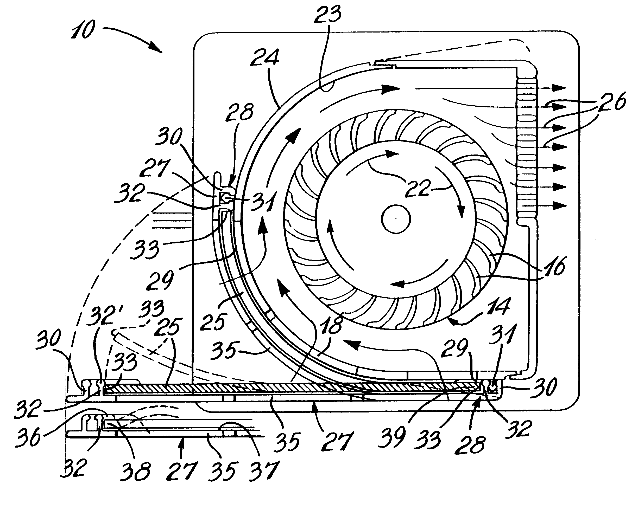
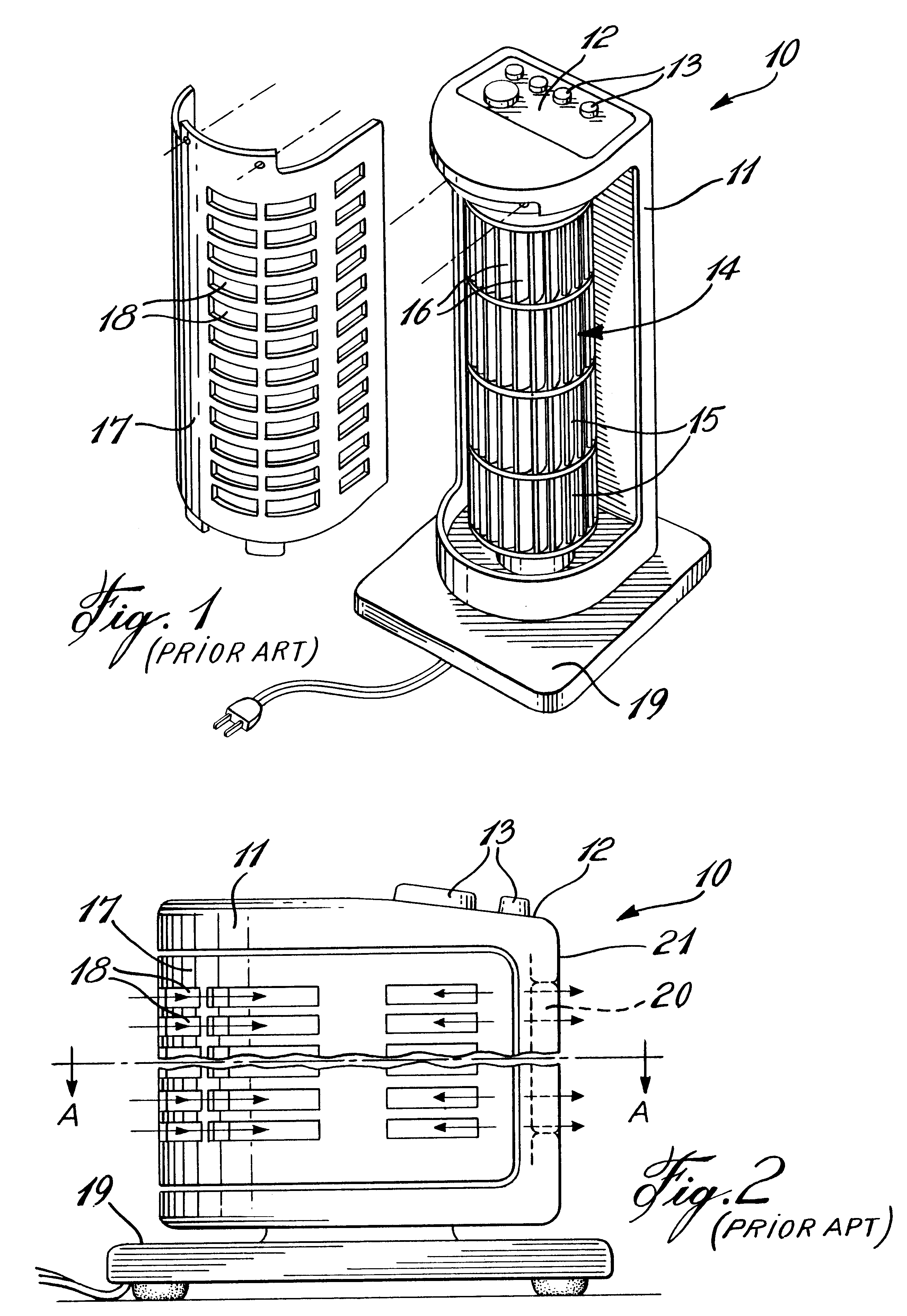
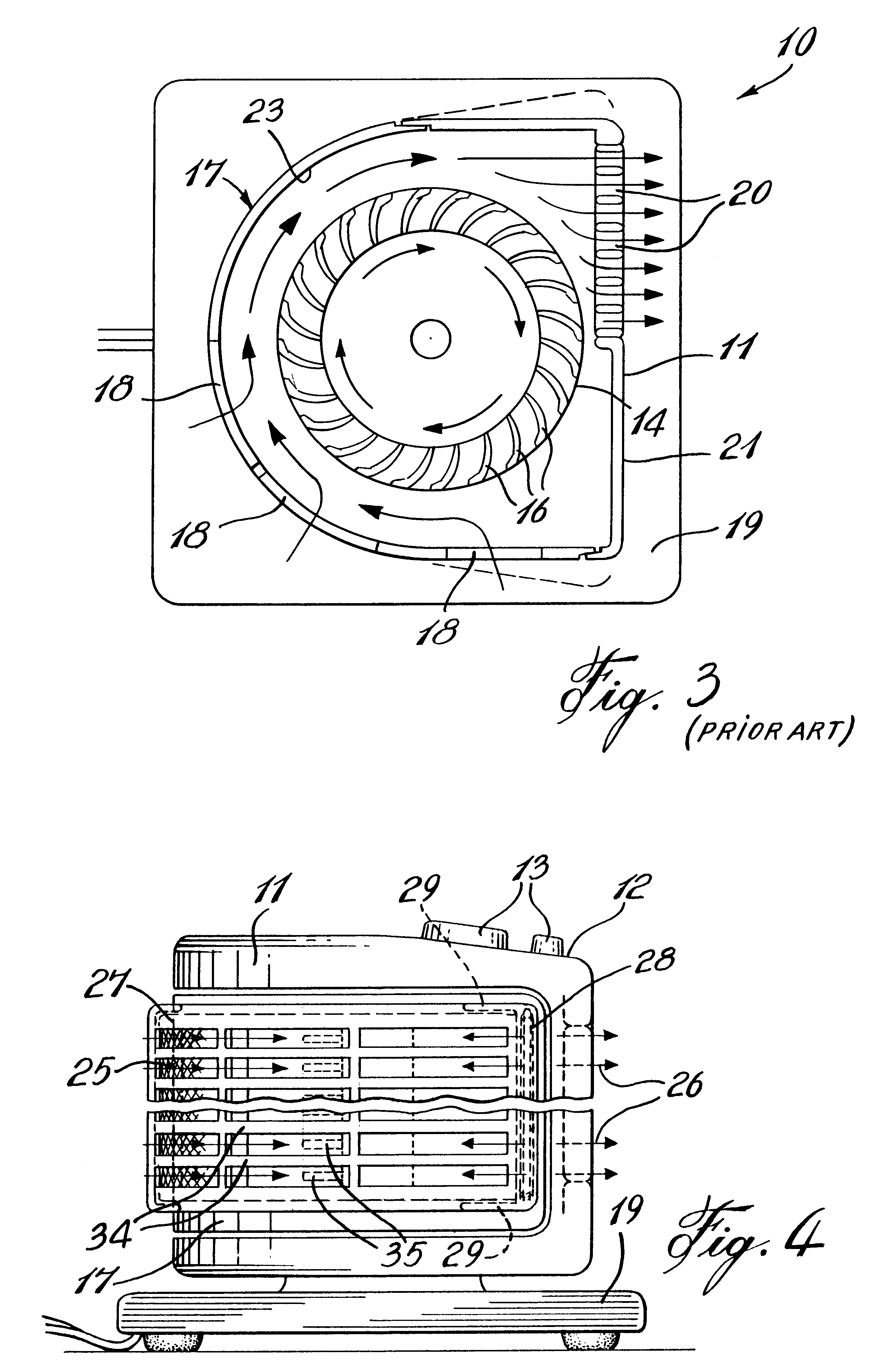
Referring now to the drawings and more particularly to FIGS. 1 to 3, there is shown generally at 10, a vertical fan of the prior art and comprised essentially of an elongated housing 11 having a control panel 12 on a top end face thereof provided with the usual controls and switches 13 whereby to control the operation of the cylinder fan 14 supported vertically therein. The cylinder rotor fan 14 is usually constructed of similar sections 15, each of which is provided with a plurality of curved fan blades 16. A detachable rear panel 17 having a ribbed air inlet opening 18 is also provided for access to the interior of the housing to permit cleaning thereof. A flat support base 19 constitutes a support means to maintain the tower vertically upright on a support surface.

As shown in FIG. 3, the housing 11 is further provided with outlet openings 20 in a front wall 21 thereof whereby upon actuation of the fan 14, which rotates in a clockwise direction as indicated by arrows 22, air is dr...


PUM

PropertyMeasurementUnit
Forceaaaaaaaaaa
Pressureaaaaaaaaaa
Flow rateaaaaaaaaaa

Abstract

A vertical air blowing fan having an air filter is described. The vertical fan has an elongated housing provided with a foot support for maintaining the housing upright. The housing is provided with an air inlet opening and an air outlet opening. A cylindrical fan is provided in the housing for drawing ambient air in the inlet opening and out through the outlet opening in a substantially tangential path inside the housing to create a substantial airflow in an area outside the housing. A filter retention member secures a filter frame curved over and against the air inlet opening. The air filter membrane is removably engageable across the opening. The filter membrane is capable of holding its shape when held in position. The filter membrane is retained outwardly curved tight against the air inlet opening of the housing wall whereby the filter delineates a convex shape against the air being drawn into the inlet opening to resist deformation. It is noted that all the ambient air is accordingly drawn through the filter.

Description

The present invention relates to a vertical blowing fan adapted with an air filter whereby to purify the ambient air ventilated by the vertical fan.Vertical fans are known in the art and have a single function and that is to circulate ambient air in an area where the fan is located in order to create a vertical air current to ventilate and refresh a room or a person. This is particularly desirable during summer months when it is very warm in a room. These vertical fans usually have an elongated partly curved housing having a long cover in a rear portion thereof in order to provide access to its interior parts to permit the fan cylindrical rotor, the motor and the interior walls of the housings to be cleaned. The fans have a long cylindrical rotor fans having a plurality of curved vertical fan blades and these are somewhat difficult and time consuming to clean. These fans also displace dust and foreign particles in the ambient air and this is not desirable to maintain a room clean. I...

Claims


Application Information

Patent Timeline
IPC IPC(8): B01D46/10B01D46/54
CPCB01D46/543B01D2279/50B01D2273/30
Inventor BOULVA, PAUL
Owner BOULVA PAUL
Learn More