Gradient based motion estimation

a technology of motion estimation and gradient, applied in the field of motion estimation, can solve the problems of real-time estimation of horizontal gradient, meaningless gradient estimation, and vertical aliasing which confuses vertical gradient estimation

Inactive Publication Date: 2002-02-05
HB COMM UK LTD
View PDF7 Cites 51 Cited by
  • Summary
  • Abstract
  • Description
  • Claims
  • Application Information

AI Technical Summary

Problems solved by technology

In practice, in the absence of additional processing, this can only really be done for the horizontal gradient.
Effectively this is vertical sub-sampling resulting in vertical aliasing which confuses the vertical gradient estimate.
This would render any gradient estimate meaningless.
Filtering cannot remove all the aliasing from these signals which will therefore result in erroneous vertical gradient estimates and, therefore, incorrect estimates of the motion vector.
Prefiltering an image sequence results in blurring.
Hence small details in the image become lost.
This has two consequences, firstly the velocity estimate becomes less accurate since there is less detail in the picture and secondly small objects cannot be seen in the prefiltered signal.
This does, indeed, improve vector accuracy but it does not overcome the other disadvantage of prefiltering, that is, that small objects cannot be seen in the prefiltered signal, hence their velocity cannot be measured.
No amount of subsequent vector refinement, using hierarchical techniques, will recover the motion of small objects if they are not measured in the first stage.
The image gradients for a single pixel do not provide enough information to determine the motion vector for that pixel.
Small regions produce detailed vector fields of low accuracy and vice versa for large regions.
The direct implementation of gradient motion estimation, discussed herein in relation to FIGS. 2 and 3, can give wildly erroneous results.
Such behaviour is extremely undesirable.
These problems occur when there is insufficient information in a region of an image to make an accurate velocity estimate.
In such circumstances it is either not possible to measure velocity or only possible to measure velocity normal to the edge.
It is attempting to estimate the complete motion vector, when insufficient information is available, which causes problems.
Numerically the problem is caused by the 2 terms in the denominator of equation 4 becoming very similar resulting in a numerically unstable solution for equation 3.
The direct solution of equation 6 would involve daunting computational and hardware complexity.
The gradient motion estimator described above is undesirably complex.
The situation is made worse by the fact that many of the signals have a very wide dynamic range making the functional blocks illustrated much more difficult to implement.
Alternatively Z could be .phi..sup.-1 (ie. assuming no noise), but this would not apply the Martinez technique and would give inferior results.
The use of inaccurate motion vectors, in performing motion compensate temporal interpolation, results in objectionable impairments to the interpolated image.
This may, in part, explain why motion compensated processing is typically, unreliable for certain types of input image.
By contrast taking larger regions in a block matching motion estimator does not necessarily increase the vector accuracy (assuming the selected vector is correct), it does however reduce the chance of measuring a `spurious` vector.
This would be very awkward for large picture expansions as very large region averaging filters (38,42) would be required.

Method used


Image

  • Gradient based motion estimation
  • Gradient based motion estimation
  • Gradient based motion estimation

Examples


Embodiment Construction

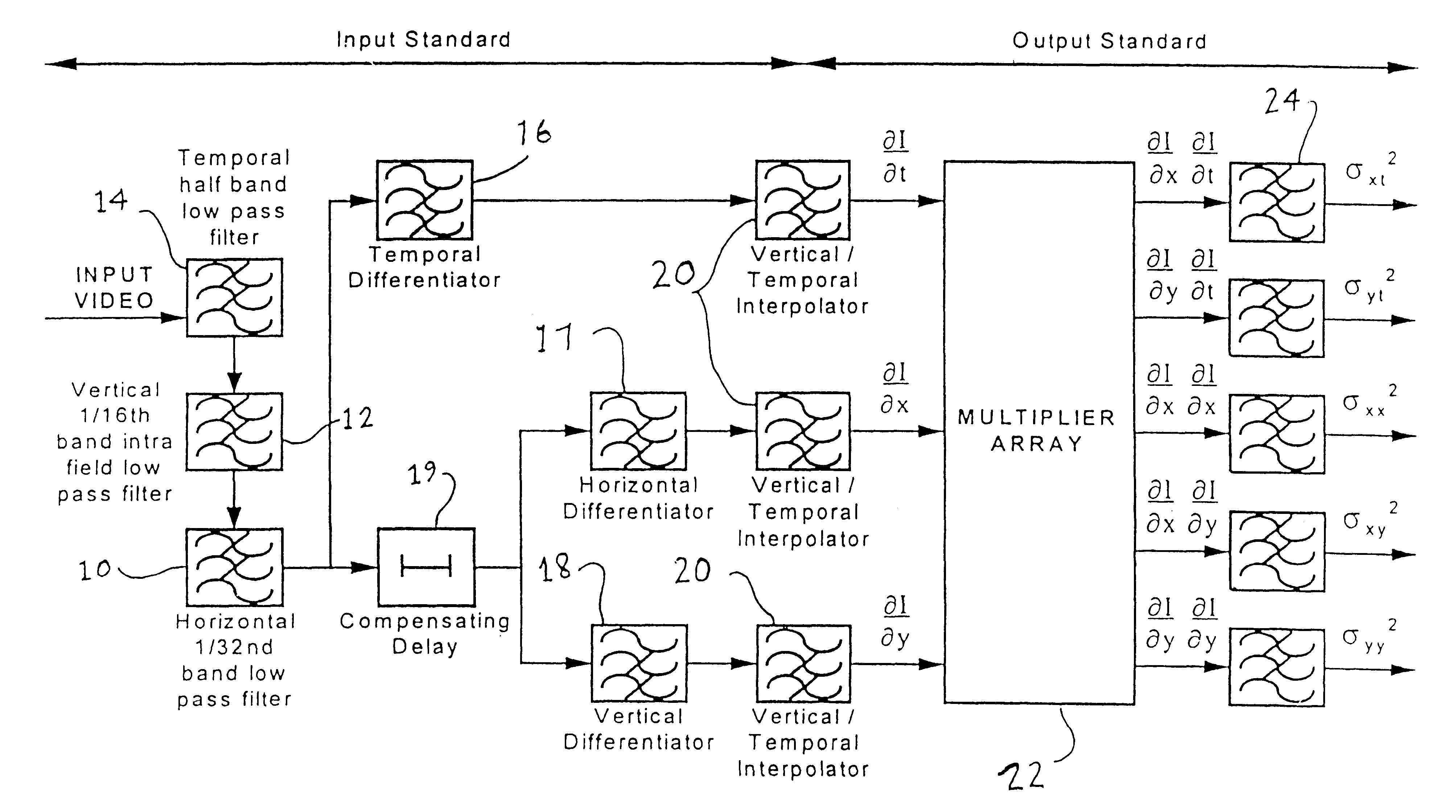
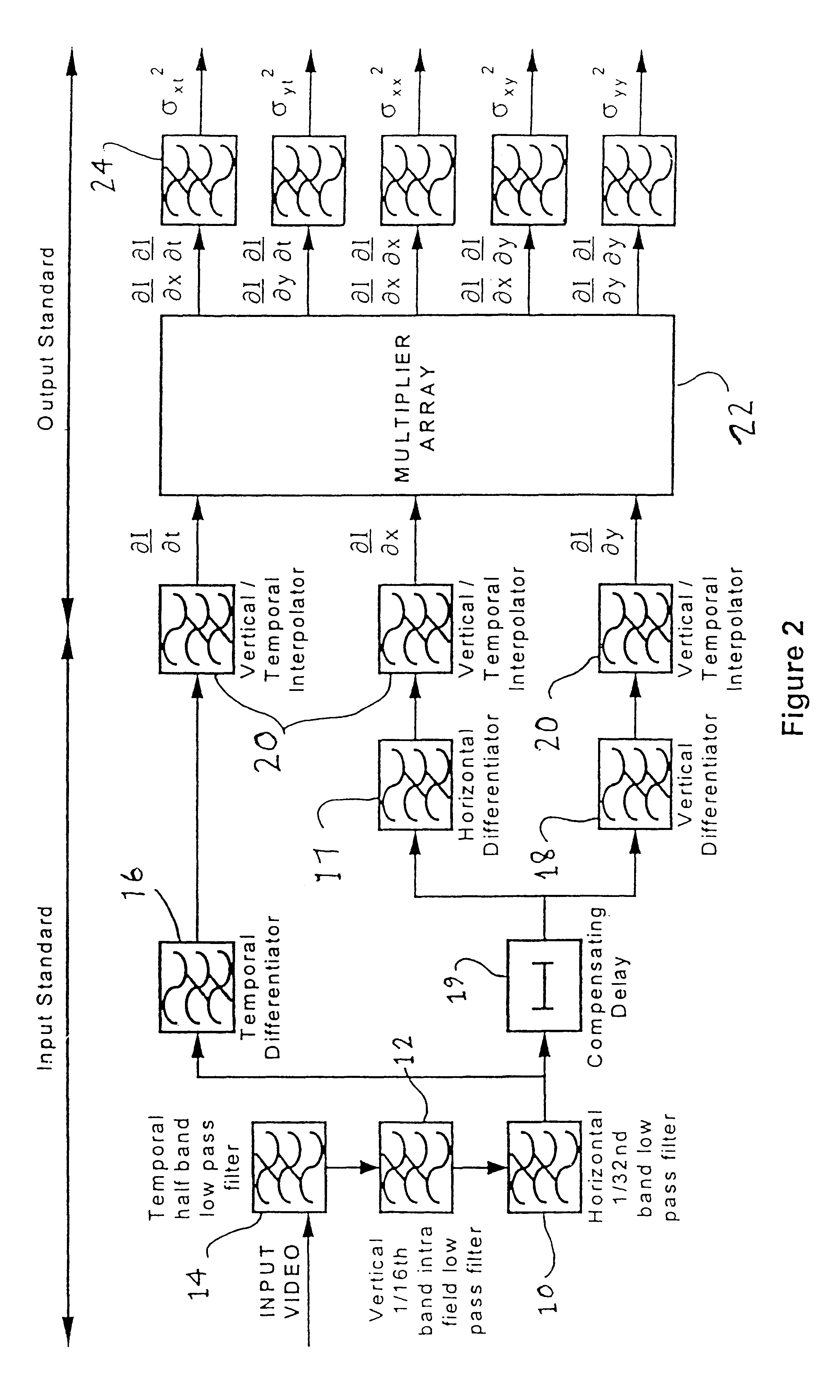
This example provides a brief specification for a gradient motion estimator for use in a motion compensated standards converter. The input for this gradient motion estimator is interlaced video in either 625 / 50 / 2:1 or 525 / 60 / 2:1 format. The motion estimator produces motion vectors on one of the two possible input standards and also an indication of the vector's accuracy on the same standard as the output motion vectors. The motion vector range is at least .+-.32 pixels / field. The vector accuracy is output as both a `spread vector` and a `confidence signal`.

A gradient motion estimator is shown in block diagram form in FIGS. 6 & 7 above. Determination of the measurement error, indicated by `spread vectors` and `confidence` are shown in FIGS. 9 & 10. The characteristics of the functional blocks of these block diagrams is as follows:

Input Video:

4:2:2 raster scanned interlaced video.

luminance component only

Active field 720 pixel.times.288 or 244 field lines depending on input standard.

Lu...


PUM


Abstract

A technique for generating motion vectors in video and film signal processing uses constraint equation based motion estimation. Simplifications of the processing and hardware are made possible by generating motion vectors based on the normalized constraint equation. The temporal and spatial image gradients are calculated using temporal and spatial differentiators (16, 17, 18). An angle (theta) corresponding to the orientation of the spatial image gradient vector and the motion speed (vn) in the direction of the vector are calculated using apparatus including a rectangular to polar coordinate converter (32). theta and vn are the parameters of the normalized constraint equation.

Description

1. Field of the InventionThe invention relates to a technique for estimating motion vectors for a video or film sequence and may be used for example in a motion estimator for use with a standards converter or a video compression system.2. Description of the Related ArtGradient motion estimation is one of three or four fundamental motion estimation techniques and is well known in the literature (references 1 to 18). More correctly called `constraint equation based motion estimation` it is based on a partial differential equation which relates the spatial and temporal image gradients to motion.Gradient motion estimation is based on the constraint equation relating the image gradients to motion. The constraint equation is a direct consequence of motion in an image. Given an object, `object(x, y)`, which moves with a velocity (u, v) then the resulting moving image, I (x, y, t) is defined by Equation 1;I(x,y,t)=object (x-ut, y-vt)This leads directly to the constraint equation, Equation 2...

Claims


Application Information

Patent Timeline
Patent Type & Authority Patents(United States)
IPC IPC(8): G06T7/20H04N7/32H04N7/01
CPCG06T7/2066G06T7/269
Inventor BORER, TIMOTHY JOHN
Owner HB COMM UK LTD
Why Eureka
Try Eureka