Periscope using common optical path to have stabilized panoramic view

a technology of panoramic view and optical path, applied in the field of periscope, can solve the problems of large and expensive periscope, time delay, vehicle moving much more slowly,

Inactive Publication Date: 2002-02-12
NAT CHUNG SHAN INST SCI & TECH
View PDF4 Cites 30 Cited by
  • Summary
  • Abstract
  • Description
  • Claims
  • Application Information

AI Technical Summary

Problems solved by technology

Therefore, the periscope is very large and expensive.
Furthermore, due to the line of sight of each of the aforementioned elements being different from each other, extra equipment is added to calculate and adjust the parallax error, which causes time delay.
The delay might be crucial in modern warfare, and the overall weight of the vehicle will also cause the vehicle to move much more slowly.

Method used


Image

  • Periscope using common optical path to have stabilized panoramic view
  • Periscope using common optical path to have stabilized panoramic view
  • Periscope using common optical path to have stabilized panoramic view

Examples


Embodiment Construction

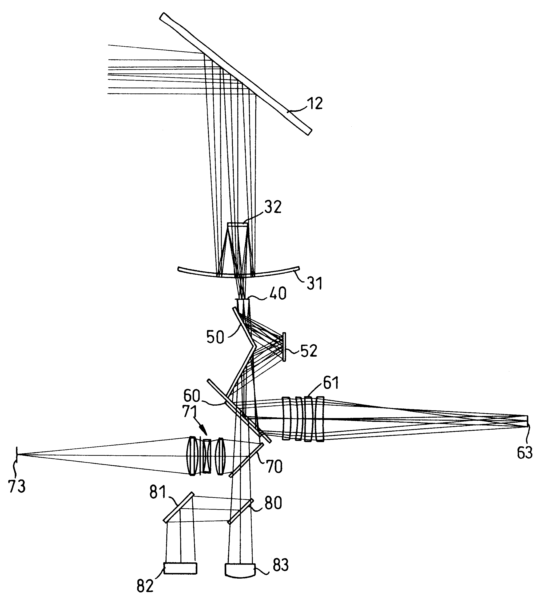
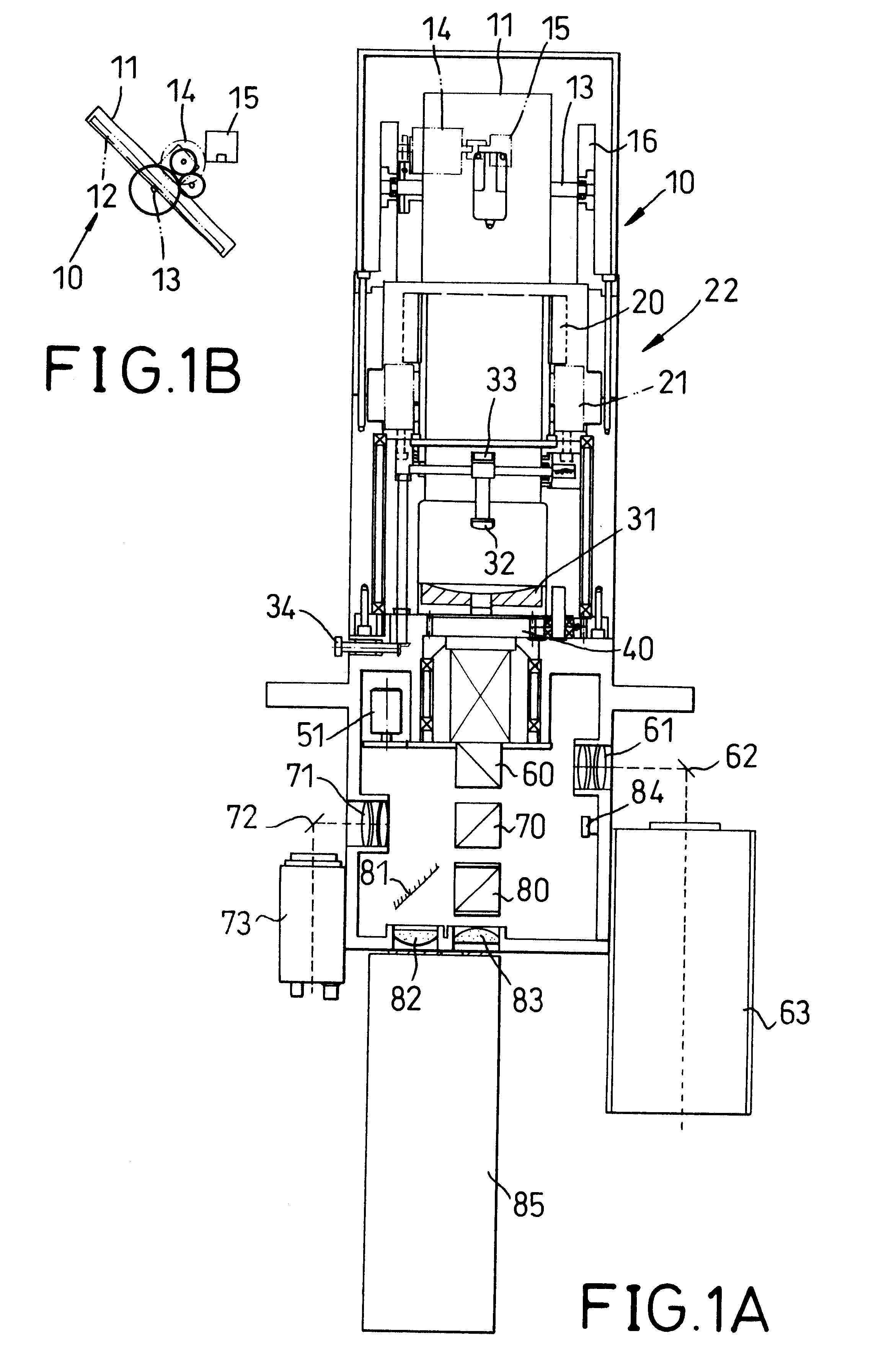
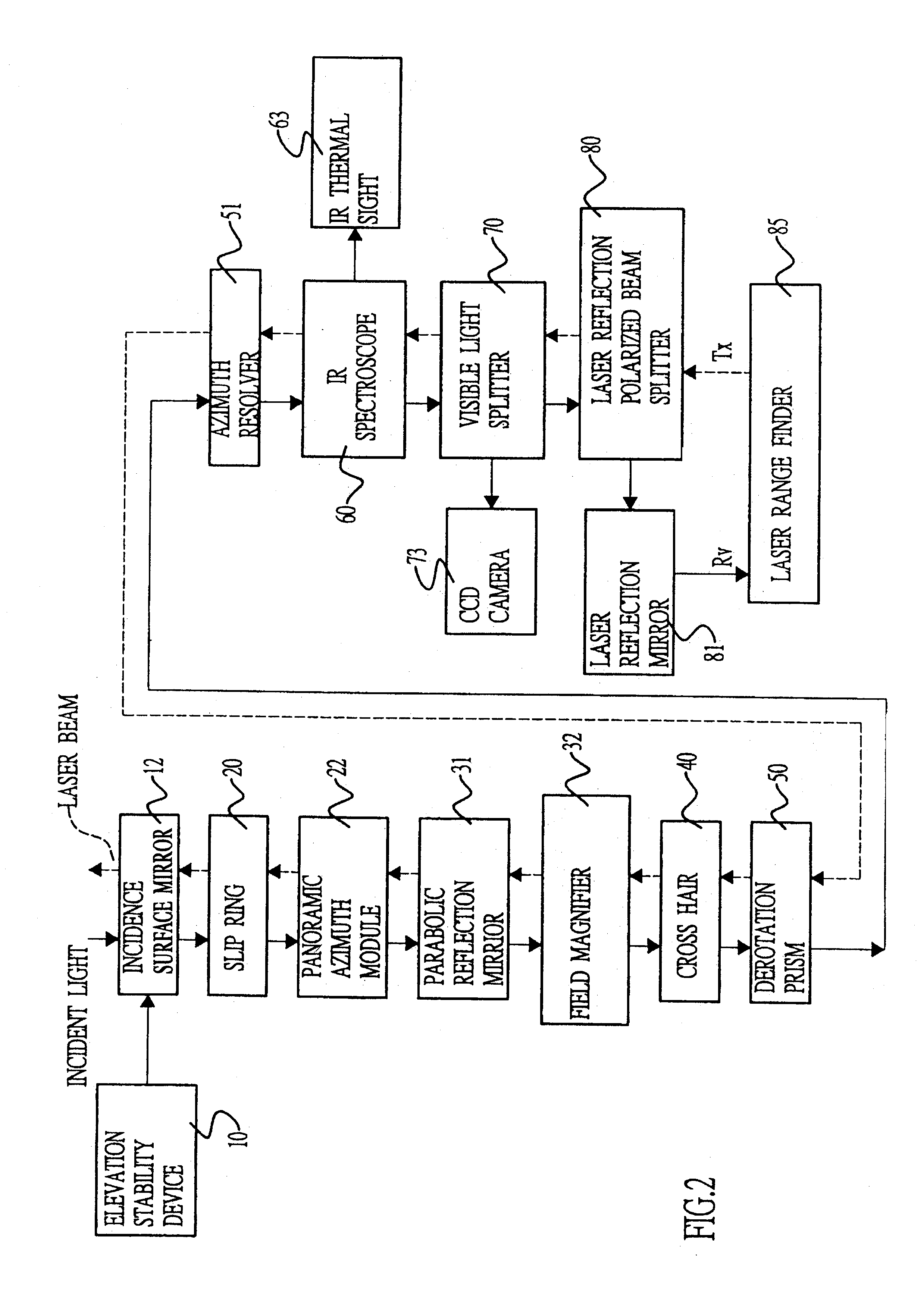
With reference to FIG. 1A, the periscope of the invention has (from top to bottom) an incidence surface mirror seat (11), a panoramic azimuth module (22), a magnifier (33), a field reflection module (FRM), a crosshair (40), a derotation prism (50), an azimuth resolver (51), an IR imager (63), a CCD camera (73) and a laser ranger finder (85). The incidence surface mirror seat (11) is supported by the incidence bracket (16) and controlled by the stabilized elevation mechanism (10). The panoramic azimuth module (22) comprises a slip ring (20) and a rotation-driving servo motor (21). The rotation-driving servo motor (21) rotates the incidence surface mirror seat (11) 360.degree. to obtain a panoramic view. The field reflection module (FRM) is composed of a parabolic reflection mirror (31) and a field magnifier (32). The IR sight device comprises an IR beam splitter (60), an IR relay lens (61), an IR reflection mirror (62) and an IR imager (63). The CCD sight device comprises a visible l...


PUM


Abstract

A periscope has an IR sight corresponding to the infrared light split from the optical splitters; a visible camera corresponding to the visible light split from the optical splitters; and a laser range finder corresponding to the laser beam for emitting and receiving the laser beam. The three different light beams are integrated to share a common optical path by means of a prism so as to reduce the size and the cost.

Description

1. Field of the InventionThe present invention relates to a periscope, and more particularly to a periscope having IR (infrared) rays, a laser beam and visible light going through the same optical path, being split by a prism and then being received by separate receivers. The periscope reduces the parts to control the optical path of different elements to reduce the cost of the periscope.2. Description of Related ArtNormally enclosed military vehicles, such as tanks and submarines, are equipped with a periscope to gather useful information without risking exposure to personnel inside the vehicle. The periscope includes a CCD camera, an IR sight and a laser range finder, all of which have independent elements with respect to each other, and each has its own optical path. Therefore, the periscope is very large and expensive. Furthermore, due to the line of sight of each of the aforementioned elements being different from each other, extra equipment is added to calculate and adjust the...

Claims


Application Information

Patent Timeline
Patent Type & Authority Patents(United States)
IPC IPC(8): G02B23/22G02B23/00G02B23/16G02B23/12G02B23/08G02B23/02
CPCG02B23/08G02B23/22G02B23/12
Inventor CHEN, PING-HOHUNG, YUNG-SHUNGHUANG, JIUN-WOEILIN, DING-TINLUO, CHIN-KUAN
Owner NAT CHUNG SHAN INST SCI & TECH
Why Eureka
Try Eureka