Method and apparatus for reducing wear in an internal combustion engine

a technology for internal combustion engines and wear reduction, which is applied in the direction of lubricant mounting/connection, lubrication indication devices, lubricant elements, etc., can solve the problems of substantial wear in engines, required operator action, and inability to achieve the effect of lubrication immediately

Inactive Publication Date: 2002-02-26
REINOSA ADAN
View PDF20 Cites 28 Cited by
  • Summary
  • Abstract
  • Description
  • Claims
  • Application Information

AI Technical Summary

Problems solved by technology

During start-up, proper lubrication is not immediately achieved since all the oil or lubricant in the normally provided engine oil galleries is evacuated by gravity action.
Other wear mechanisms account for substantial wear in engines.
These wear mechanisms are attributed mainly to suspended solid particles and chemical contaminants in the lubricating oil.
These methods introduce inconveniences such as waiting for the operating cycle to occur, required operator action, and difficult installation.
Such inconvenient time delay is irritating to the vehicle operator and in some prior art may even be dangerous should the vehicle stall and needs to re-start immediately.
Such contamination contributes substantially to engine wear and physical degradation of the engine lubricating oil.
Prior art devices are required to be larger and more complicated installations because they need to overcome the specification of quick on demand delivery of lubricating oil.
Rupture of the holding chamber inside a hot engine bay will produce a fire and environmental hazard.
These systems introduce inconvenience, safety and potential environmental problems.
Although these references partially address the problem of prelubricating the engine, there are many undesirable design drawbacks and unrecognized problems to such systems.
Additional elements in prior art increase the complexity and costs of installation and maintenance of such systems, as well as the space requirements in an already cramped engine bay.
Consequently, the size, complexity, cost and problems associated with the installation and maintenance of such systems has prevented their widespread use in most vehicles.
Another approach is U.S. Pat. No. 5,195,476, which issued to Schwarz on Mar. 23, 1993, discloses a system for prelubricating an engine by using the pump provided by the manufacturer as a means to pressurize the oil immediately before start-up, ...

Method used


Image

  • Method and apparatus for reducing wear in an internal combustion engine
  • Method and apparatus for reducing wear in an internal combustion engine
  • Method and apparatus for reducing wear in an internal combustion engine

Examples


second embodiment

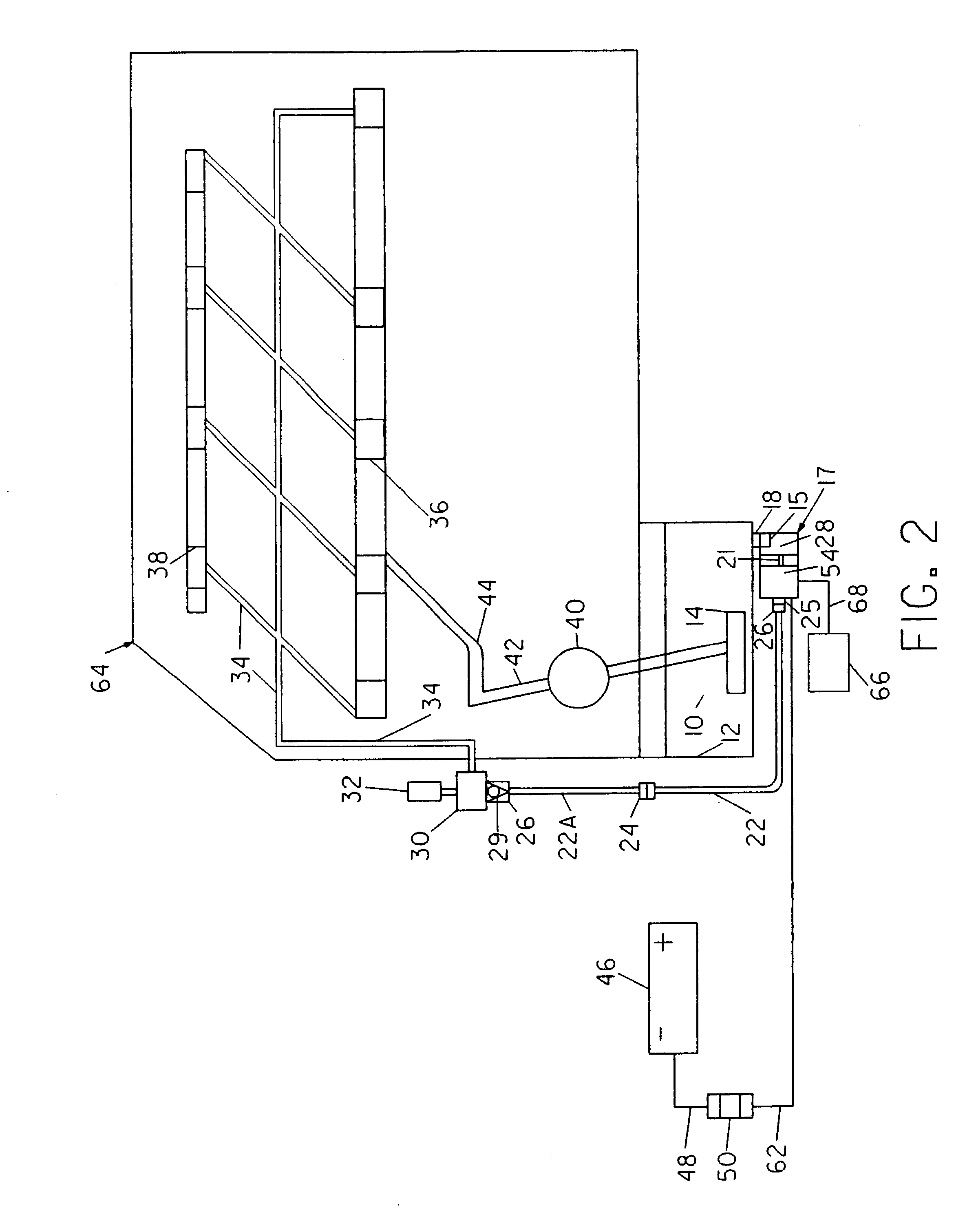
Now referring to FIG. 2, this second embodiment departs from the most preferred embodiment by having the timed pump 17, connected immediately outside of oil pan 12. Hydraulic pump 28 inlet 15 is directly connected to oil pan 12 through a modified drain plug 18. Of course, the inlet 15 can be shaped to mate directly to oil sump 12 but it is shown with plug 18 for completeness. The timed pump 17 operates exactly in the same method as described for the preferred embodiment for frequency and duration of operation in FIG. 1. Timed pump 17 is also connected to remote operator 66 through control wire for remote operation 68, and timed pump 17 is also connected to the battery as shown in FIG. 1. Now referring back to FIG. 2, hydraulic pump outlet 25 is connected through hydraulic connector 26 to a hydraulic hose or hydraulic line 22, which in turn is connected to a multiposition valve, or three-way hydraulic valve 24. Still referring to FIG. 2, three-way hydraulic valve 24 allows for mutual...

third embodiment

Now referring to FIG. 3, this third embodiment departs from the preferred in that it does not have and integrated pump and controller, but that the electronic controller 54 is remote from hydraulic pump 28. Electronic controller 54 is electrically connected to hydraulic pump 28 by means of electrical control wire harness 21. The method of operation is identical to the one disclosed in FIG. 1 and FIG. 2, but connection to engine block is the same as FIG. 2

fourth embodiment

Now referring to FIG. 4, this fourth embodiment shows another schematic of connection and description of another embodiment of my automatic method and apparatus for reducing wear in an internal combustion engine. Lubricating oil 10 contained in oil sump 12, is allowed to flow through a hydraulic coupling 20 to allow evacuation of lubricating oil 10 from oil sump 12 and flow through a hydraulic fluid line or hose 22B. Hydraulic fluid line 22B is connected to a quick disconnect hydraulic coupling 27, which is connected to hydraulic line 22C. Part 22C is connected to hydraulic connector 26 and this is connected to pump inlet 15 of hydraulic pump 28. Hydraulic pump 28 outlet 25 is connected to hydraulic line 22D by hydraulic connector 26. Hydraulic line 22D is connected to a three-way hydraulic valve 24. From valve 24, embodiment of FIG.4 is identical in the description of connection to the engine block as the one disclosed in FIG. 2 embodiment and can also use the connection method of ...


PUM


Abstract

An apparatus for reducing wear in an internal combustion engine includes a pump, a control element, an external controller. The apparatus of the preferred embodiment is intended to be located inside an internal combustion engine, thereby eliminating most hardware. The control element is connected to a normally provided battery and automatically switches control power from the battery to the electric pump according to a programmed control operating cycle program, and is operatively independent of ignition switch activation or operator action. The inlet of the pump is immersed in oil inside the normally provided engine oil sump. The lubricating fluid is pumped through the high arrestance filter, yielding a substantially contaminant free lubricating fluid which flows into the normally provided engine lubricating gallery. The external controller, such as a wireless remote control, is provided to activate the pump remotely upon demand. In a second embodiment, a three-way valve is provided to facilitate evacuation of the oil sump for the purpose of an oil change by overriding automatic operation of the electric pump by a local control switch. In the second embodiment the inlet of the electric pump is dimensioned to be affixed and fluidly connected to the oil sump. An assembly adapter is disclosed that facilitates installation of the present invention, allows for easy fluid access to the engine oil gallery, and prevents backflow of the periodically injected oil which is done acording to the present invention operating strategy. The method discloses the periodic injection of oil into the lubricating galleries, whereby by continuously repeating the operating cycle the engine is automatically protected from wear by simultaneous priming, purifying and prelubricating.

Description

BACKGROUND-FIELD OF THE INVENTIONThe present invention relates to internal combustion engines, and more particularly to improvements, to a method and apparatus for admitting a lubricating fluid into the existing lubrication system of those engines for prelubricating the engine before start-up to reduce wear on the moving parts of the engine.BACKGROUND-DESCRIPTION OF THE PRIOR ARTInternal combustion engines depend for their proper lubrication to be already running. During start-up, proper lubrication is not immediately achieved since all the oil or lubricant in the normally provided engine oil galleries is evacuated by gravity action. After the elapsing of a period of time, the oil adhered to the slidable working surfaces, engine lubricating galleries, and parts, drains to the bottom reservoir or oil sump. This leaves the slidable working surfaces unprotected from wear during the next start-up. McDonnell Douglas has performed tests which indicate that up to 90 percent of the wear in ...

Claims


Application Information

Patent Timeline
IPC IPC(8): F01M5/00F01M5/02F01M11/03
CPCF01M5/02F01M5/025F01M2011/036
Inventor REINOSA, ADAN
Owner REINOSA ADAN
Why Eureka
Try Eureka