Optical attenuator

an optical attenuator and optical technology, applied in the field of optical attenuators, can solve the problems of affecting the performance of optical signals

Inactive Publication Date: 2002-02-26
LUCENT TECH INC
View PDF6 Cites 244 Cited by
  • Summary
  • Abstract
  • Description
  • Claims
  • Application Information

AI Technical Summary

Problems solved by technology

Many optical communication systems are lossy in that the optical fibers used therein scatter (or absorb) portions of the optical signals transmitted therealong (about 0.1-0.2 dB / km).
After the optical signals propagating along the optical fiber experience multiple cycles of power losses followed by amplification, power variations between the different wavelengths of the optical signals potentially occur.
If not corrected, these power variations may cause adjacent wavelengths to interfere (cross-talk) with each other.
Interference between adjacent wavelengths of the optical signals is a potential source of transmission errors.
One problem with optical attenuators that include reflective plates relates to their insertion loss.
Reflective plates with very flat surfaces are difficult to fabricate.
However, for a torsional plate structure, the torsional members are fragile such that the equilibrium rotation of the reflective plate potentially drifts after each "on / off" cycle.
Cavity heights greater than about 5 .mu.m are undesirable because large bias voltages (greater than about 50 volts) are needed to generate the electrostatic force between the membrane and the bottom surface of the cavity.

Method used


Image

  • Optical attenuator
  • Optical attenuator
  • Optical attenuator

Examples


Embodiment Construction

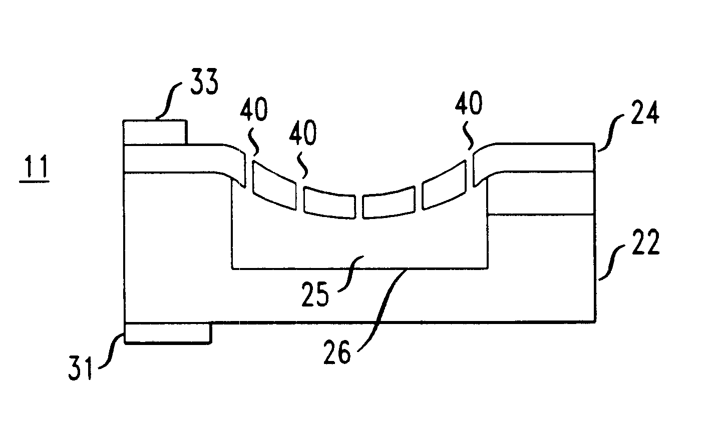
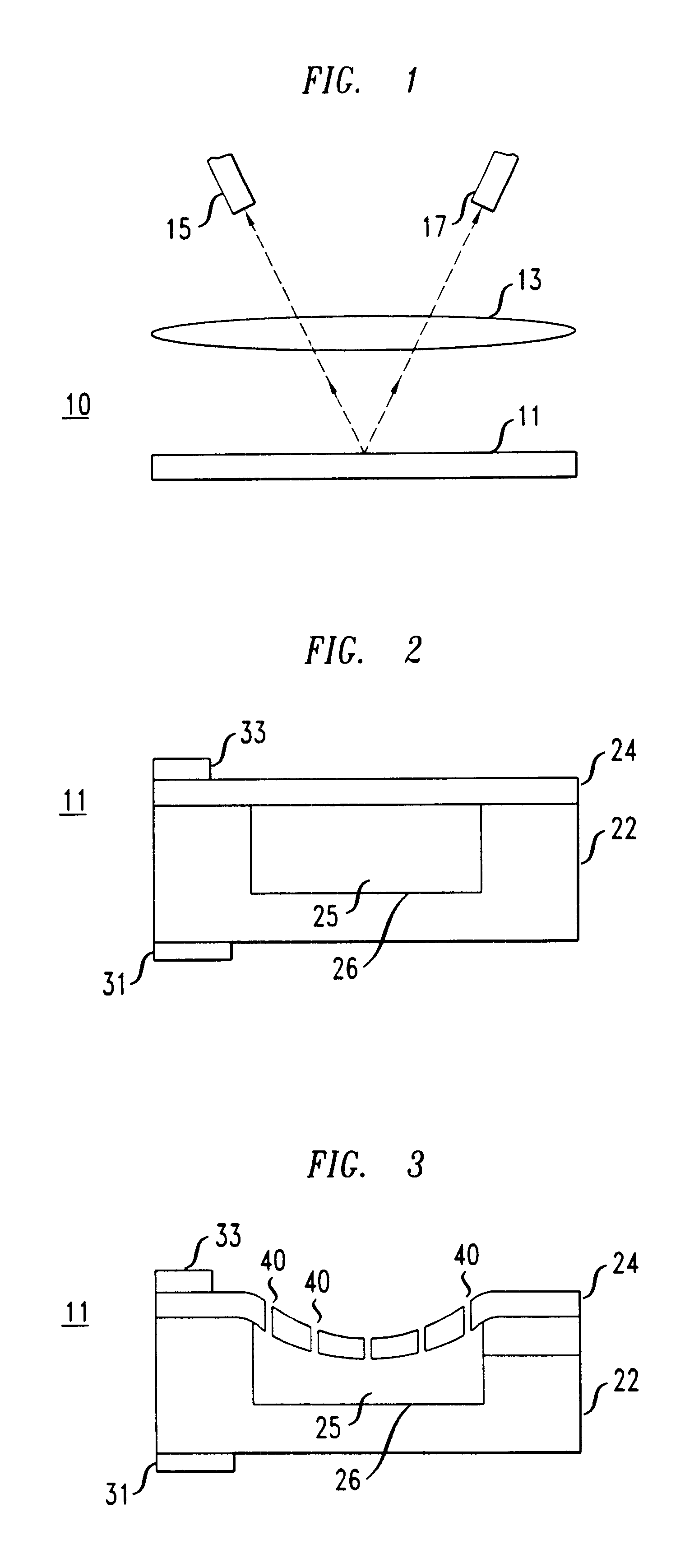
An optical attenuator having the structure depicted in FIG. 2 was simulated. The cavity was assumed to be circular with a diameter of about 1000 .mu.m. The height of the cavity was assumed to be about 5 .mu.m. The membrane covering the cavity was assumed to be a layer of silicon nitride about 0.2 .mu.m thick and covered with a thin gold layer. The silicon nitride had a tensile stress assumed to be about 50 MPa. A bias voltage of about 28 volts was assumed to be applied between the metal on the silicon nitride membrane and the bottom surface of the cavity. Calculations performed using a bias voltage of about 28 volts determined that the midpoint of the silicon nitride membrane would be depressed about 1.5 .mu.m into the cavity (about 30% of the cavity height).

The input and the output optical fibers were located about 4 mm (millimeters) away from the membrane surface and arranged so that the optical signals impinged on the membrane about 275 .mu.m away from the center point of the cav...


PUM


Abstract

An optical attenuator having a structure in which a membrane covers a cavity formed on a substrate is disclosed. The membrane covering the cavity formed in the substrate is movable relative to the bottom surface of the cavity constituting a deformable mirror. Movement of the membrane relative to the bottom surface of the cavity attenuates optical signals impinging on the surface thereof. The movement of the membrane relative to the bottom surface of the cavity attenuates impinging optical signals by controlling the angle at which such impinging optical signals are reflected from the membrane surface.

Description

The present invention relates generally to optical communication systems and more particularly to optical attenuators.DESCRIPTION OF THE RELATED ARTOptical communication systems typically include a variety of optical fiber-coupled devices (e. g., light sources, photodetectors, switches, attenuators, amplifiers, and filters). The optical fiber-coupled devices transmit optical signals in the optical communications systems. Some optical signals that are transmitted in such optical communications systems have many different wavelengths (frequencies). Digital or analog data is transmitted on the different wavelengths of the optical signals.Many optical communication systems are lossy in that the optical fibers used therein scatter (or absorb) portions of the optical signals transmitted therealong (about 0.1-0.2 dB / km). When portions of the optical signals transmitted on the optical fibers are scattered (or absorbed), the power associated with such optical signals is reduced. To compensat...

Claims


Application Information

Patent Timeline
Patent Type & Authority Patents(United States)
IPC IPC(8): G02B26/00G02B26/08G02B6/35G02B6/26
CPCG02B6/266G02B26/0825G02B26/001G02B6/3516G02B6/3518G02B6/357G02B6/3594G02B6/352
Inventor GREYWALL, DENNIS STANLEY
Owner LUCENT TECH INC
Why Eureka
Try Eureka