Optical fiber switch

a technology of optical fiber switch and optical fiber end, which is applied in the field of optical fiber switch, can solve the problems of limited lifetime of these devices, laser energy loss, and optical damage to the optical fiber end

Inactive Publication Date: 2002-02-26
LOS ALAMOS NATIONAL SECURITY
View PDF5 Cites 143 Cited by
  • Summary
  • Abstract
  • Description
  • Claims
  • Application Information

AI Technical Summary

Benefits of technology

To achieve the foregoing and other objects, and in accordance with the purposes of the present invention, as embodied and broadly described herein, there has been invented a device which employs an alternating sequence of laser light modulators, such as Pockels cells, and laser light polarizers to distribute laser light for injection into a plurality of optical fibers. This invention is particularly useful for sequential ignition of a number of internal combustion engine cylinders or turbine engine ignitors.

Problems solved by technology

These devices typically have lack of reproducibility in the alignment of focused laser light onto the faces of the optical fibers, leading to laser energy losses or optical damage to the optical fiber ends.
Since they contain moving mechanical parts, the lifetimes of these devices are limited and they eventually fail due to mechanical wear.
Also, electro-optical laser light switching devices that depend upon waveguide technology have speeds which are limited by the time required for deformation and recovery of a piezoelectric crystal (many milliseconds); thus, the rate at which light can be switched from one fiber to another is similarly limited.

Method used


Image

  • Optical fiber switch
  • Optical fiber switch
  • Optical fiber switch

Examples


Embodiment Construction

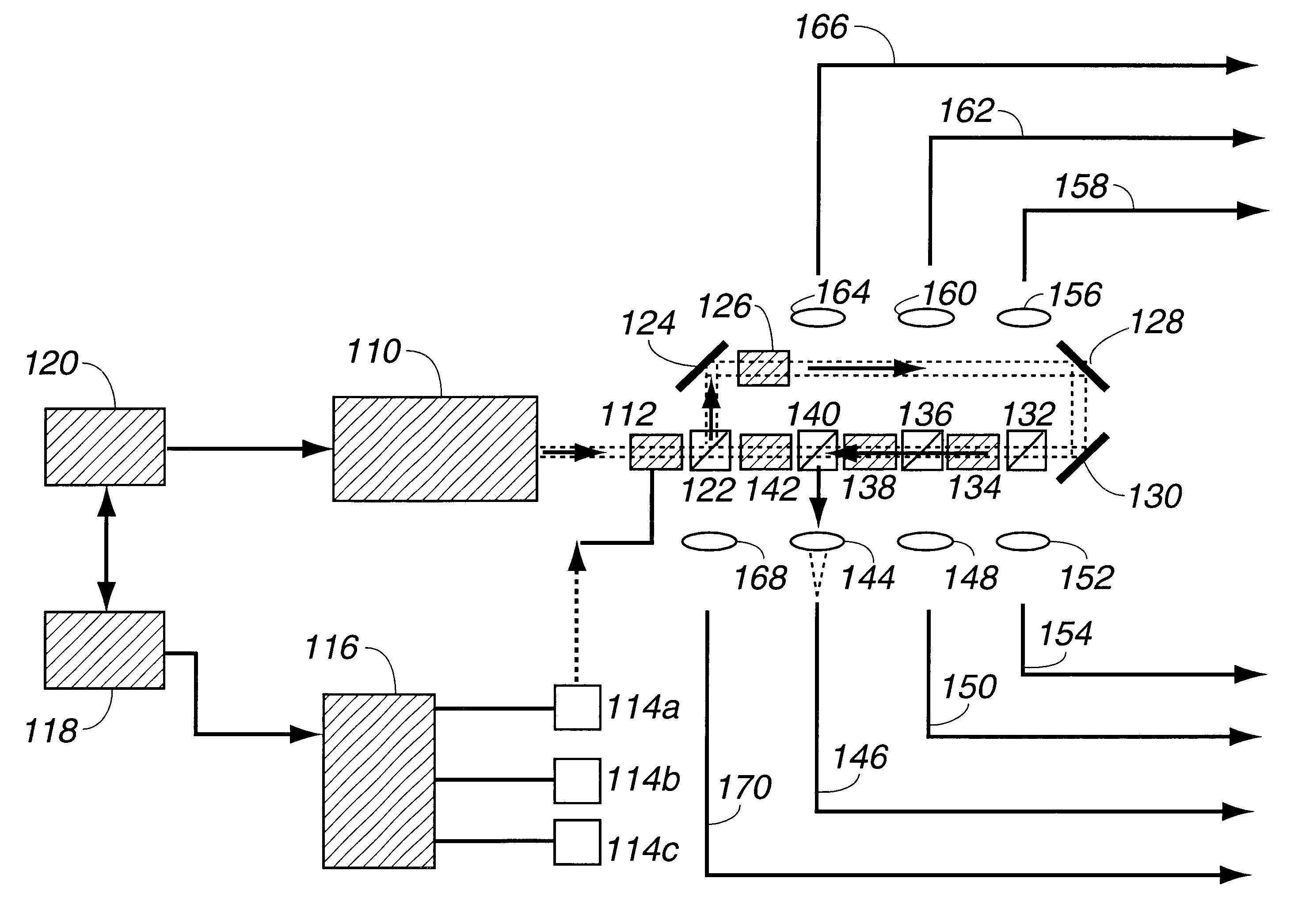
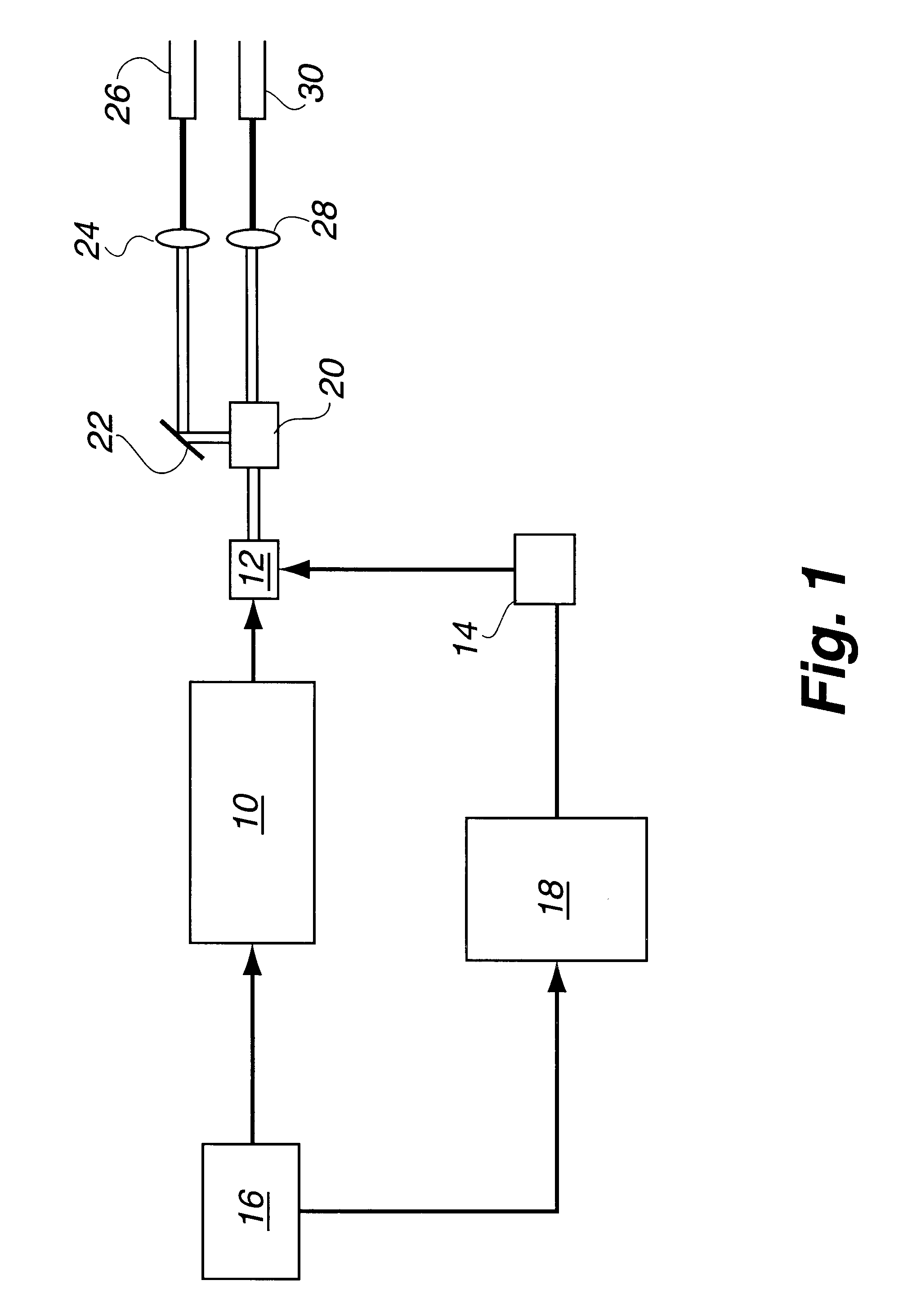
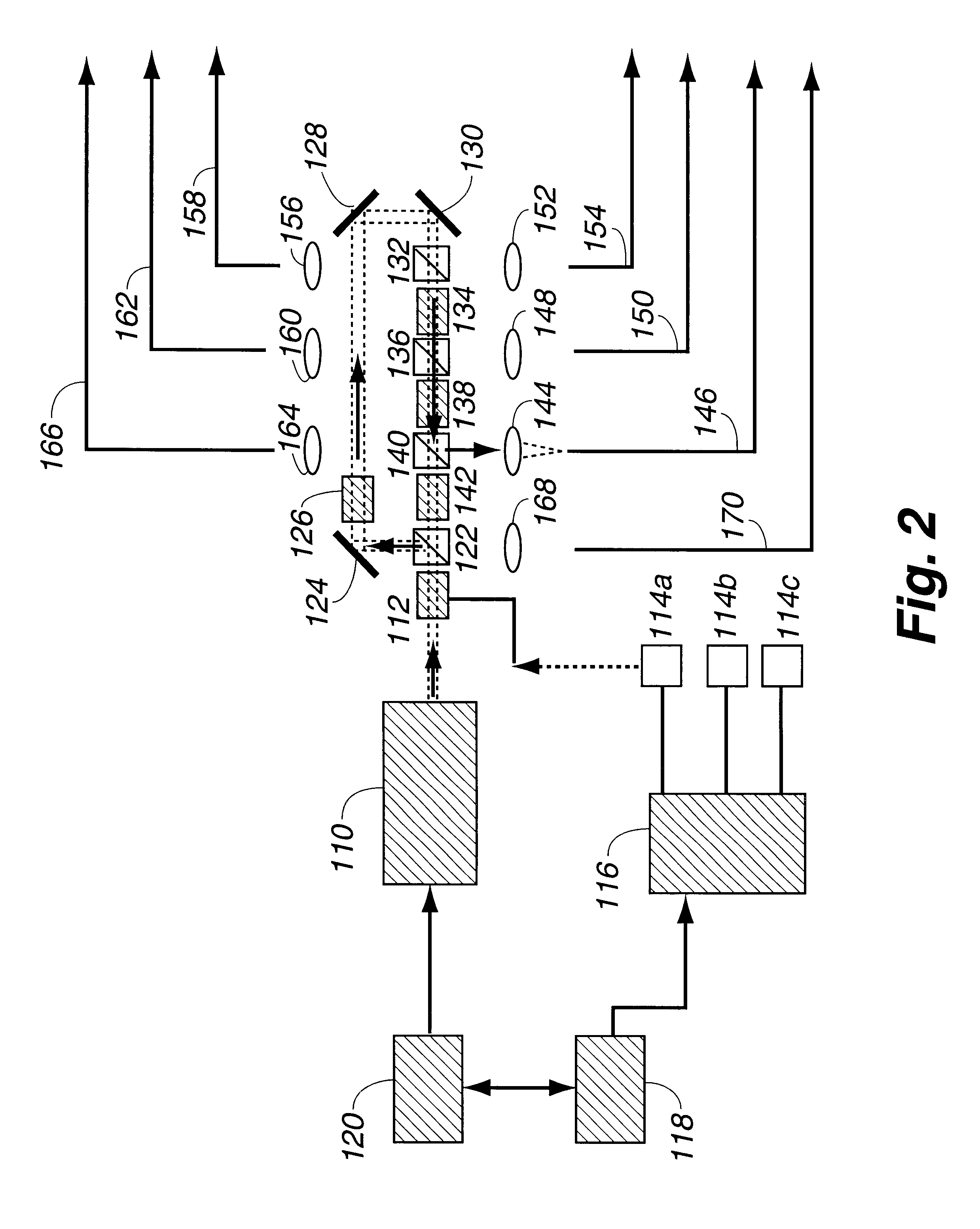
In the present invention, an optical fiber switch operated by electrical activation of at least one laser light modulator paired with at least one laser light polarizer is used for the sequential injection of laser light from a single laser into a plurality of optical fibers for transport to a number of devices where it is desired to deliver a laser beam.

The invention comprises an alternating series of at least one laser light modulator and at least one laser light polarizer arranged so as to direct linearly polarized laser light beams from a laser first through at least one laser light modulator. The laser light modulator is intermittently activated in accordance with signals from a timing module and firing sequence controller. The polarization state of the light leaving the laser light modulator is controlled by application of the voltage (or other electrical field) to the material of the laser light modulator. Thus the laser light modulator provides the means for rotating the pol...


PUM

PropertyMeasurementUnit
voltageaaaaaaaaaa
wavelengthaaaaaaaaaa
angleaaaaaaaaaa

Abstract

Optical fiber switches operated by electrical activation of at least one laser light modulator through which laser light is directed into at least one polarizer are used for the sequential transport of laser light from a single laser into a plurality of optical fibers. In one embodiment of the invention, laser light from a single excitation laser is sequentially transported to a plurality of optical fibers which in turn transport the laser light to separate individual remotely located laser fuel ignitors.The invention can be operated electro-optically with no need for any mechanical or moving parts, or, alternatively, can be operated electro-mechanically. The invention can be used to switch either pulsed or continuous wave laser light.

Description

This invention relates to laser light switching technology.Optical fiber laser light switching devices currently used generally rely upon rotating or moving mirrors or translating optical fibers to permit the selective injection of high peak power laser light into multiple fibers. These devices typically have lack of reproducibility in the alignment of focused laser light onto the faces of the optical fibers, leading to laser energy losses or optical damage to the optical fiber ends. Since they contain moving mechanical parts, the lifetimes of these devices are limited and they eventually fail due to mechanical wear. Also, electro-optical laser light switching devices that depend upon waveguide technology have speeds which are limited by the time required for deformation and recovery of a piezoelectric crystal (many milliseconds); thus, the rate at which light can be switched from one fiber to another is similarly limited.There is a need for faster, more durable, accurate, reliable ...

Claims


Application Information

Patent Timeline
Patent Type & Authority Patents(United States)
IPC IPC(8): G02F1/03G02F1/01G02B6/35
CPCG02B6/351G02F1/0327G02B6/3548G02B6/3594G02B6/3572
Inventor EARLY, JAMES W.LESTER, CHARLES S.
Owner LOS ALAMOS NATIONAL SECURITY
Why Eureka
Try Eureka