Skylight membrane with diverter

Inactive Publication Date: 2002-03-12
SWEARINGEN MICHAEL R
View PDF24 Cites 80 Cited by
  • Summary
  • Abstract
  • Description
  • Claims
  • Application Information

AI Technical Summary

Benefits of technology

FIG. 3 is a perspective view of the present invention installed on a roof skylight showing the direction of water flow on a pitched roof. As the water cascades down a pitched roof any protrusions encountered cause the water to backup, the amount of water is a direct variable of the intensity of the rain. The large exposed edge of a skylight causes a considerable amount of blockage. This is also a more severe problem in colder climates because this edge is a natural for the formation of ice barriers. The present invention being a single formed member will prevent any seepage between the skylight and the rough framed opening within the roof. The present invention also has an angularly protruding rim extending across the up slope side of the collar to prevent any water from wicking up between the elastomeric collar element and the skylight frame. There are also ridge members spaced apart from the skylight extending above and below the horizontal line of the up slope collar surface which will prevent any lateral flow of water coming off of the up slope side.
FIG. 4 is a perspective view of the present invention installed on the roof with the skylight ready to be installed. Also shown, is the skylight elastomeric member having the elastomeric collar element encompassing the skylight roof opening framing members. Als

Problems solved by technology

Also, the heat of the elastomeric material of the collar during the second stage molding process causes some

Method used


Image

  • Skylight membrane with diverter
  • Skylight membrane with diverter
  • Skylight membrane with diverter

Examples


Embodiment Construction

)

In order that the invention may be more fully understood, it will now be described, by way of example, with reference to the accompanying drawings in which FIGS. 1 through 8 illustrate the present invention being a skylight membrane with a water diverter.

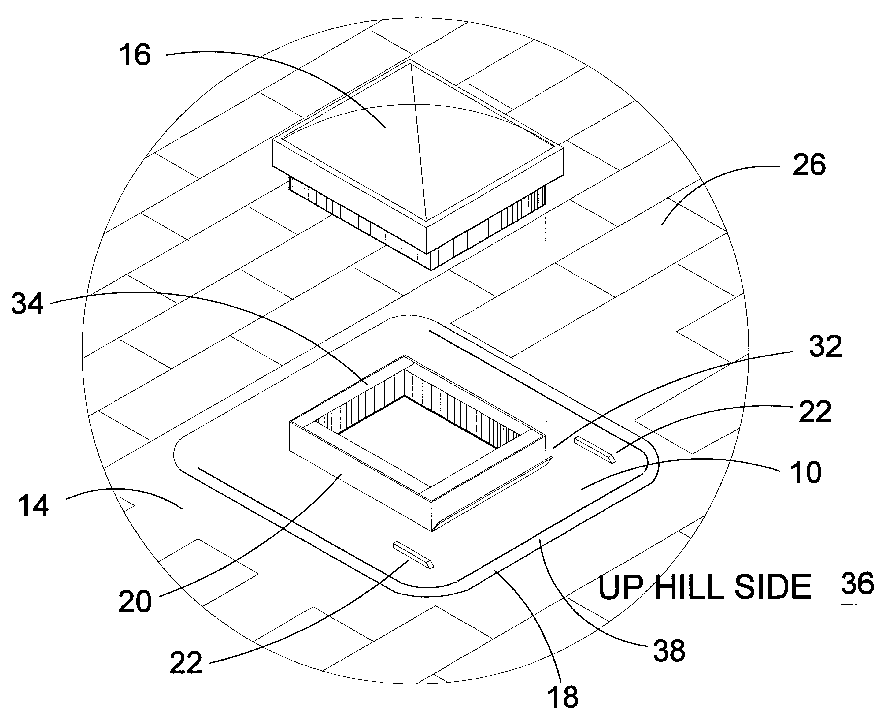
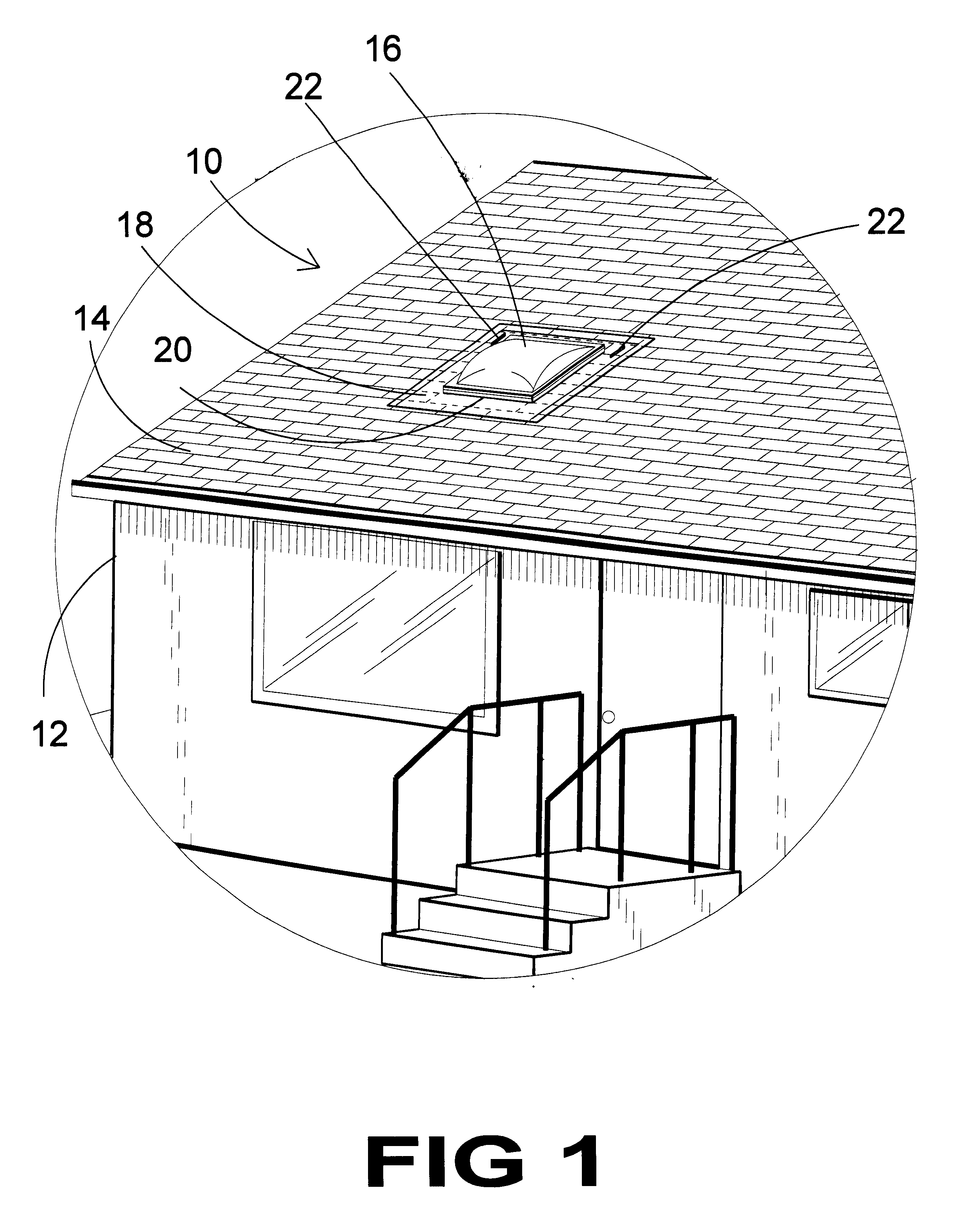
Turning to FIG. 1, shown therein is an illustrative view of the present invention 10 installed. Shown is a house 12 having a pitched roof 14 having a skylight. The skylight elastomeric membrane 10 is installed over the skylight rough opening having a planar membrane element 18 and collar membrane element 20. The collar membrane element 20 has an angularly protruding turnback edge (not shown) extending across the up slope side and spaced above the shingles of roof 14. The planar membrane element 18 has two spaced apart ridges 22 extending above and below the turnback.

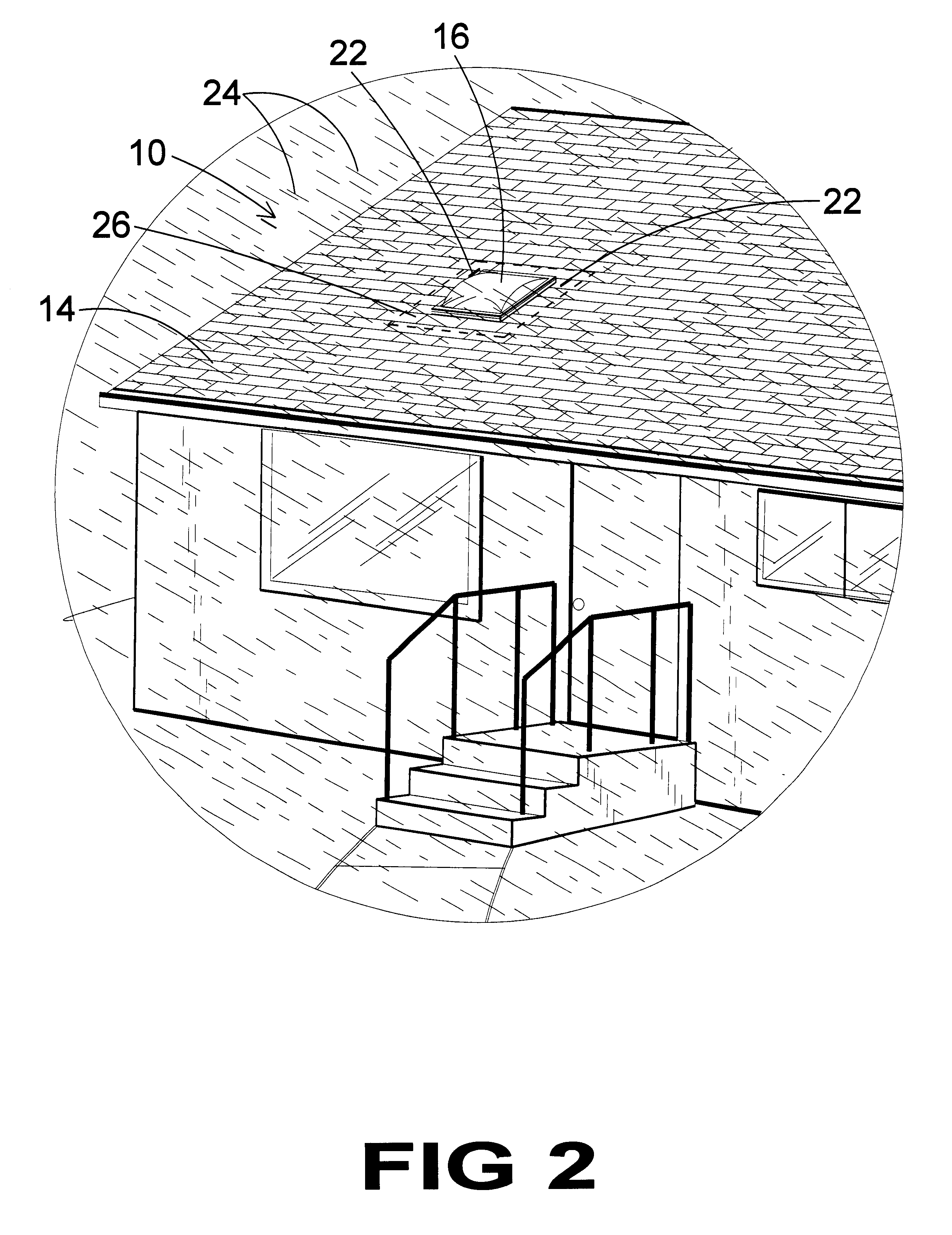
Turning to FIG. 2, shown therein is an illustrative view of the present invention 10 showing the flow of water during a rain storm 24. The skylight elastomeric membrane...


PUM


Abstract

The present invention 10 discloses an elastomeric skylight membrane molded as a single piece comprising a planar element 18 for sealably engaging roof sheathing 26 and a centrally positioned collar element 20 for sealably engaging the rough opening framing members 34. The skylight collar membrane 20 is inserted over the framed rough opening for a skylight 16 having the elastomeric collar element tightly engaging the framing members 34 and of substantially the same height as the rough opening frame members. The planar element 18 engages the roof sheathing 26 and is fixedly attached thereto by any means well known within the art. Positioned across the up slope side 36 of the collar 20 is an angularly protruding edge 32 for preventing water from wicking between the skylight frame 34 and the skylight membrane 10. To prevent lateral flow from the up slope edge 36 of the skylight 16 there are two spaced apart ridges 22 transversely positioned to the turnback collar sides extending above and below the horizontal edge 30 of the up slope side 36. The diverter ridges 22 spaced away form the turnback side 32 obstruct lateral water flow returning it to a downhill flow. The planar element 18 further has a bead 38 on three sides near its periphery that will redirect any water that has accumulated between the skylight membrane and shingles to a downward flow.

Description

1. Field of the InventionThe present invention relates generally to roof flashing and, more specifically, to an elastomeric skylight membrane formed as a single piece having a planar membrane element having a centrally positioned membrane collar element enclosing an aperture. The skylight membrane is inserted over the framed rough opening for a skylight having the membrane collar element tightly engaging the framing members and of substantially the same height as the rough opening framing members. The planar membrane element engages the roof sheathing and is fixedly attached thereto by any means well known within the art. In addition, a turnback edge is exteriorly positioned on the up slope side of the membrane collar element for the purpose of preventing water from wicking between the skylight frame and the skylight membrane. This is especially necessary as the slope of the roof increases.The water which encounters the turnback side of the collar has a tendency to flow tangently. T...

Claims


Application Information

Patent Timeline
IPC IPC(8): E04D13/14E04D13/03E04D13/147
CPCE04D13/1475E04D13/0315
Inventor SWEARINGEN, MICHAEL R
Owner SWEARINGEN MICHAEL R
Why Eureka
Try Eureka