Automatic position-control valve assembly

a technology of automatic position control and valve assembly, which is applied in the direction of valve operating means/releasing devices, servomotors, transportation and packaging, etc., can solve the problems of difficult maintenance, the use of such automatic position control valve assemblies, and the need for extremely clean air for valve position transducers

Inactive Publication Date: 2002-03-12
HENRY PRATT CO +1
View PDF11 Cites 59 Cited by
  • Summary
  • Abstract
  • Description
  • Claims
  • Application Information

AI Technical Summary

Benefits of technology

The invention is described and explained in more detail below using an embodiment shown in the drawings. The described and drawn features can be used individually or in preferred combinations in other embodiments of the invention. The foregoing and other objects, features and advantages of the invention will be apparent from the following more particular description of a preferred embodiment of the invention, as illustrated in the accompanying drawings in which reference characters refer to the same parts throughout the different views. The drawings are not necessarily to scale, emphasis instead being placed upon illustrating principles of the invention in a clear manner.

Problems solved by technology

A difficulty that sometimes develops in use of such automatic position-control valve assemblies occurs when a valve position transducers fail.
In this regard, valve position transducers require extremely clean air, which is difficult to maintain in some industries.
Such valve position transducers, for example, will not work with regular compressed air.
In any event, they sometimes have control signal problems.
When valve position transducers have such problems, or otherwise fail, they sometimes drive valve elements to incorrect positions, with drastic results.
Further, it has often been inconvenient to replace such components, because replacement parts have not always been immediately available and / or technicians with the ability to replace them have not been available.
Thus, operations have often been shut down for long periods of time.

Method used


Image

  • Automatic position-control valve assembly
  • Automatic position-control valve assembly
  • Automatic position-control valve assembly

Examples


Embodiment Construction

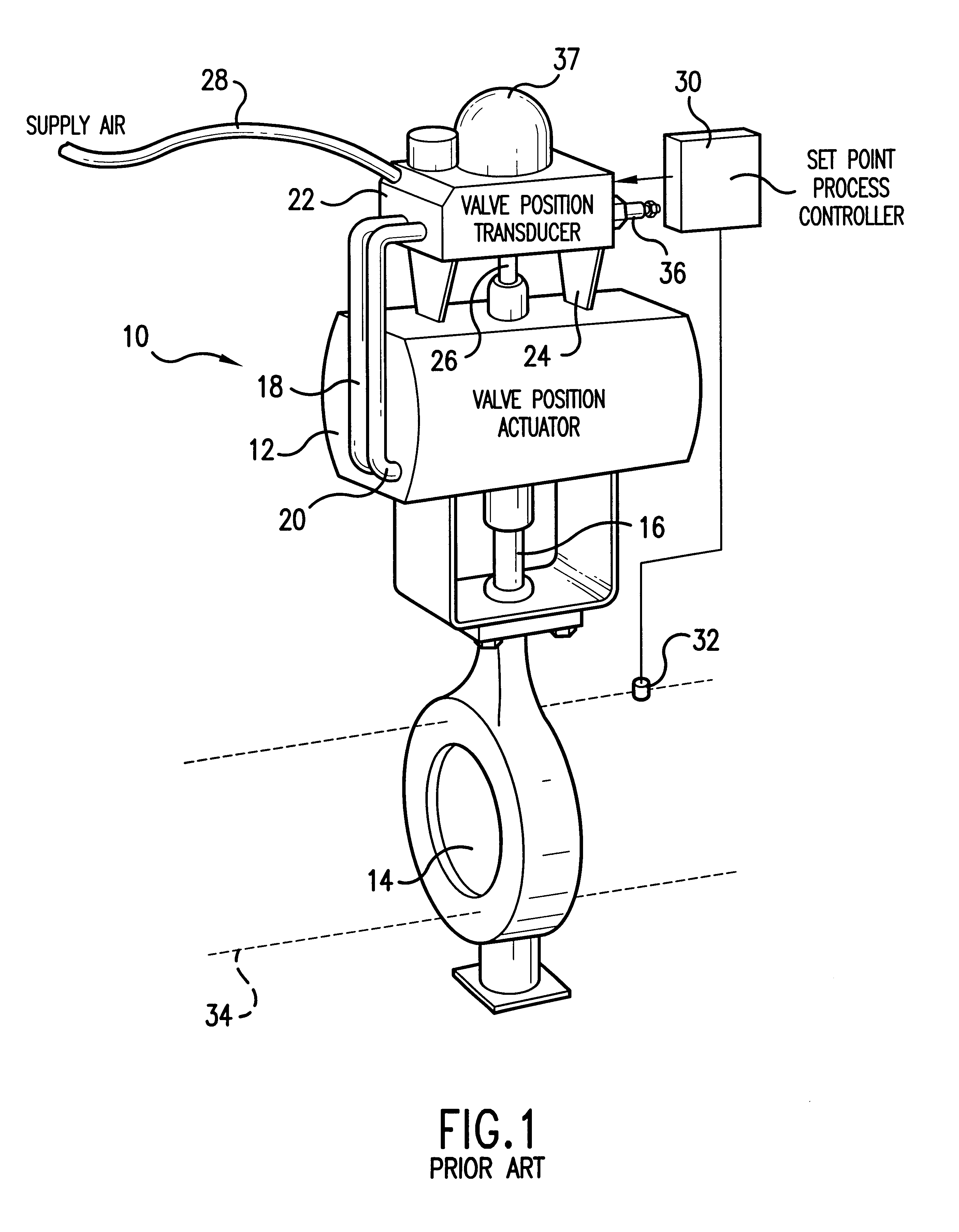
First, the structure and operation of a prior-art automatic position-controlled valve assembly 10 will be described with reference to FIG. 1.

The prior-art automatic position-controlled valve assembly 10 includes a valve position actuator 12 which controls the position of a valve element of a butterfly valve 14 via a valve-control shaft 16. The valve position actuator 12 is basically a piston working in a cylinder, with the piston being moved in one direction when pressurized air, or other fluid, is provided on a first pressurized-air line 18 and in an opposite direction when pressurized air is provided on a second pressurized-air line 20. It should be understood that the piston (not shown) need not be a linearly-moving piston, but can also be a rotating member which is caused to rotate by pressurized fluid. In any event, the piston is linked to the shaft 16 for causing the shaft 16 to rotate in a first direction when the piston is moved in a first direction and in a second, opposite...


PUM


Abstract

According to principles of this invention, an override controller is structured for being placed in pressurized fluid lines between a valve position transducer and a valve position actuator of an automatic position-controlled valve assembly, with the override controller receiving uncontrolled supply pressurized fluid and having an exhaust. The override controller receives pressurized fluid at first and second inlet ports from the valve position transducer and furnishes this pressurized fluid to the valve position actuator through first and second outlet ports for controlling the position of the valve during normal operation. However, valve mechanisms of the override controller can also be placed in positions for stopping flow of pressurized fluid through the first and second inlet ports and providing fluid flow from the uncontrolled pressurized fluid to the first and second outlet ports for controlling the position of an industrial valve during override operation.

Description

This invention relates broadly to automatic position-control valve assemblies and more specifically to safety features for them.It is well known that factories and other industrial installations are increasingly automated. There are, for example, apparatus for automatically and continuously repositioning industrial valves to achieve desired fluid flows. Often desired flows change with changing conditions. For example, it may be desirable to control fluid flow so as to maintain a selected pressure, temperature, flow rate, or level. In fact, many industrial installations include fluid-condition transducers for monitoring flow (as measured by temperature, pressure, flow rate, and so forth), with electrical signals. Similarly, many industrial valves include valve position feedback potentiometers, or transducers, sometimes combined with limit switches, for providing signals which are indicative of valve positions. Normally, a valve position signal is used to provide a visual readout as t...

Claims


Application Information

Patent Timeline
Patent Type & Authority Patents(United States)
IPC IPC(8): F15B13/10F15B13/00F15B20/00F15B9/09F15B9/00F16K31/16F16K37/00
CPCF15B9/09F15B13/10F16K37/0041F16K31/16F15B20/00Y10T137/87169
Inventor MAYHEW, JOHN
Owner HENRY PRATT CO
Why Eureka
Try Eureka