Webbing retractor

a retractor and webbing technology, applied in the field of webbing retractors, can solve the problems of large apparatus as a whole, and the protrusions contacting the one having the higher rigidity are extremely small

Inactive Publication Date: 2002-03-12
KK TOKAI RIKA DENKI SEISAKUSHO
View PDF18 Cites 48 Cited by
  • Summary
  • Abstract
  • Description
  • Claims
  • Application Information

AI Technical Summary

Problems solved by technology

Since the above-described conventional webbing retractor has a large number of parts to be used, the apparatus becomes large as a whole.
However, the portion of the protrusions

Method used


Image

  • Webbing retractor
  • Webbing retractor
  • Webbing retractor

Examples


Embodiment Construction

of the Frame 20]

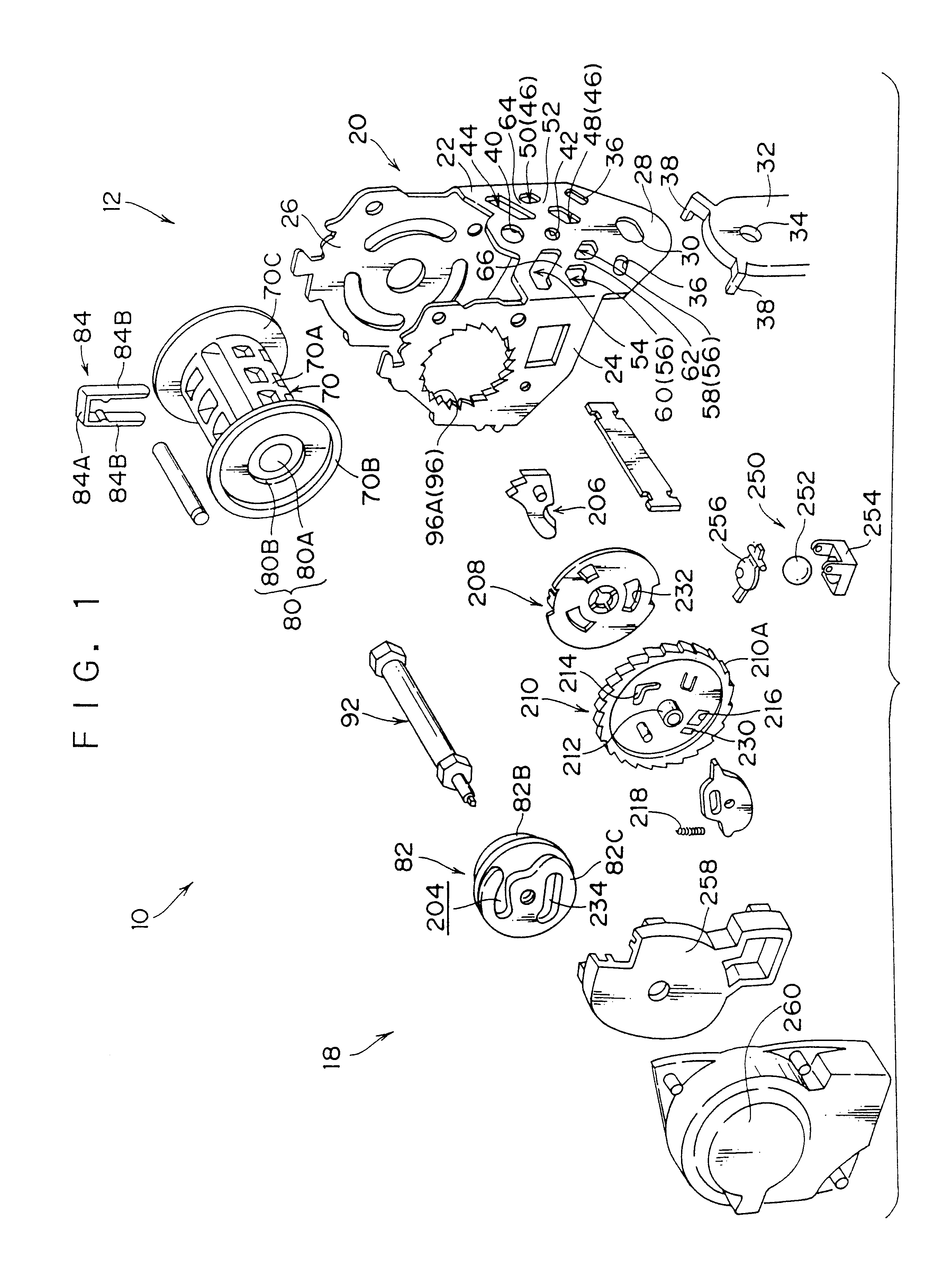
FIG. 4 is a front view of the frame 20. As shown in this figure, a side of the base portion 22 of the frame 20, which side being lower than a portion connecting the leg plates 24 and 26 is a fixing portion 28, the fixing portion 28 is in a substantially triangular shape, having a width that gradually decreases in the downward direction. In the vicinity of a peak portion thereof (the lower end portion), there is formed a bolt insertion hole 30 penetrating through in the thickness direction of the base portion 22. The bolt insertion hole 30 is an elongated hole whose longer side is along the width direction of the base portion 22. A bolt penetrates through the bolt insertion hole 30, and is fastened by a nut or the like in the state of penetrating through a penetration hole 34 of a supporting portion 32 provided in a vehicle body. Thereby, the base portion 22 is fixed to the supporting portion 32, and the webbing retractor 10 is supported by the vehicle body.

Above the ...


PUM


Abstract

An inexpensive webbing retractor is obtained by making a pretensioner and a lock device small and reducing the number of parts. A plurality of protrusions are formed on an inner peripheral portion of the bearing body, which pivotally supports a clutch portion. These protrusions are brought into linear contact with an outer peripheral portion of the clutch portion, whereby the bearing body pivotally supports the clutch portion indirectly via the protrusions. Since the protrusions are brought into linear contact with the clutch portion, the contact area becomes quite small. Hence, the protrusions are easily plastically deformed due to friction resistance with the clutch portion. Therefore, resistance that obstructs the rotation of the clutch portion becomes small, and gas pressure can be efficiently supplied for the rotation of a take-up shaft. Also disclosed is a locking device comprising a lock base attached to the winding spool, a lock plate for engagement with ratchet teeth of a frame, and a lock cover which comprises a hook portion with which the lock base is engaged, and an outer peripheral flange portion overlapping the frame.

Description

1. Field of the InventionThe present invention relates to a webbing retractor in a seat belt system for restraining an occupant in a vehicle with a webbing belt.2. Description of the Related ArtA webbing retractor constituting a main part of a so-called seat belt system for restraining an occupant in a vehicle with an elongated belt-shaped webbing belt basically comprises: a take-up shaft with which one end of the webbing belt is engaged; a frame for supporting the take-up shaft; and urging means such as a spiral coil spring or the like, for urging the take-up shaft in the direction of winding the webbing belt.In addition to the above structure, an ordinary webbing retractor is provided with a lock device for locking the take-up shaft when a vehicle enters an abrupt deceleration state, to thereby resist a force of an occupant's body, which moves toward the front of the vehicle due to inertia in the abrupt deceleration state, acting to pull out the webbing belt, and for improving the...

Claims


Application Information

Patent Timeline
IPC IPC(8): B60R22/46B60R22/405B60R22/34B60R22/28
CPCB60R22/405B60R22/4619B60R22/4676B60R22/4633B60R2022/287B60R22/28
Inventor NAGATA, TOMONORIHORI, SEIJISUMIYASHIKI, AKIRAASAGIRI, KATSUKI
Owner KK TOKAI RIKA DENKI SEISAKUSHO
Why Eureka
Try Eureka