Liquid ejection method

Inactive Publication Date: 2002-03-12
CANON KK
View PDF21 Cites 41 Cited by
  • Summary
  • Abstract
  • Description
  • Claims
  • Application Information

AI Technical Summary

Problems solved by technology

However, there is no record that a recording system which allows a bubble that is formed in an ink path to eject liquid, to become connected to the atmospheric air (hereinafter, "bubble-atmospheric air connection system" or simply, "bubble-air connection system"), has been developed enough to be put to practical use.
The conventional "bubble-air integration systems" rely on bubble explosion, but they are not stable in terms of liquid ejection.
Therefore, they cannot be put to practical use.
However, this system also has a problem that a large number of ultramicroscopic liquid droplets are generated at the same time as a primary liquid droplet is generated.
However, this patent presents this structure, in which a bubble generated in liquid by the thermal energy given by a heat generating element becomes connected to the atmospheric air, as an undesirable example of the liquid ejection head structure in which ink fails to be ejected or ink is ejected in a direction deviating from the predetermined direc

Method used


Image

  • Liquid ejection method
  • Liquid ejection method
  • Liquid ejection method

Examples


Embodiment Construction

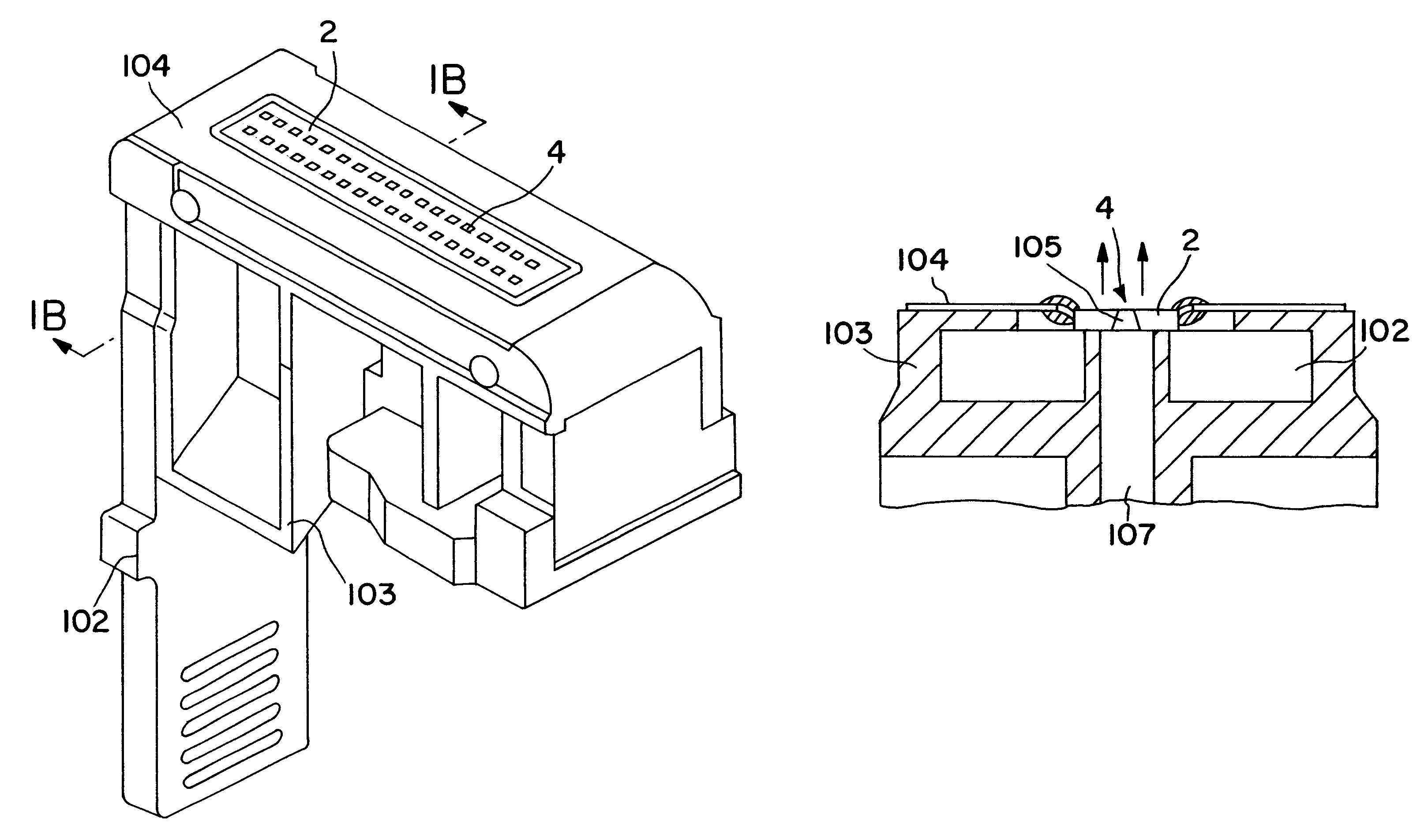
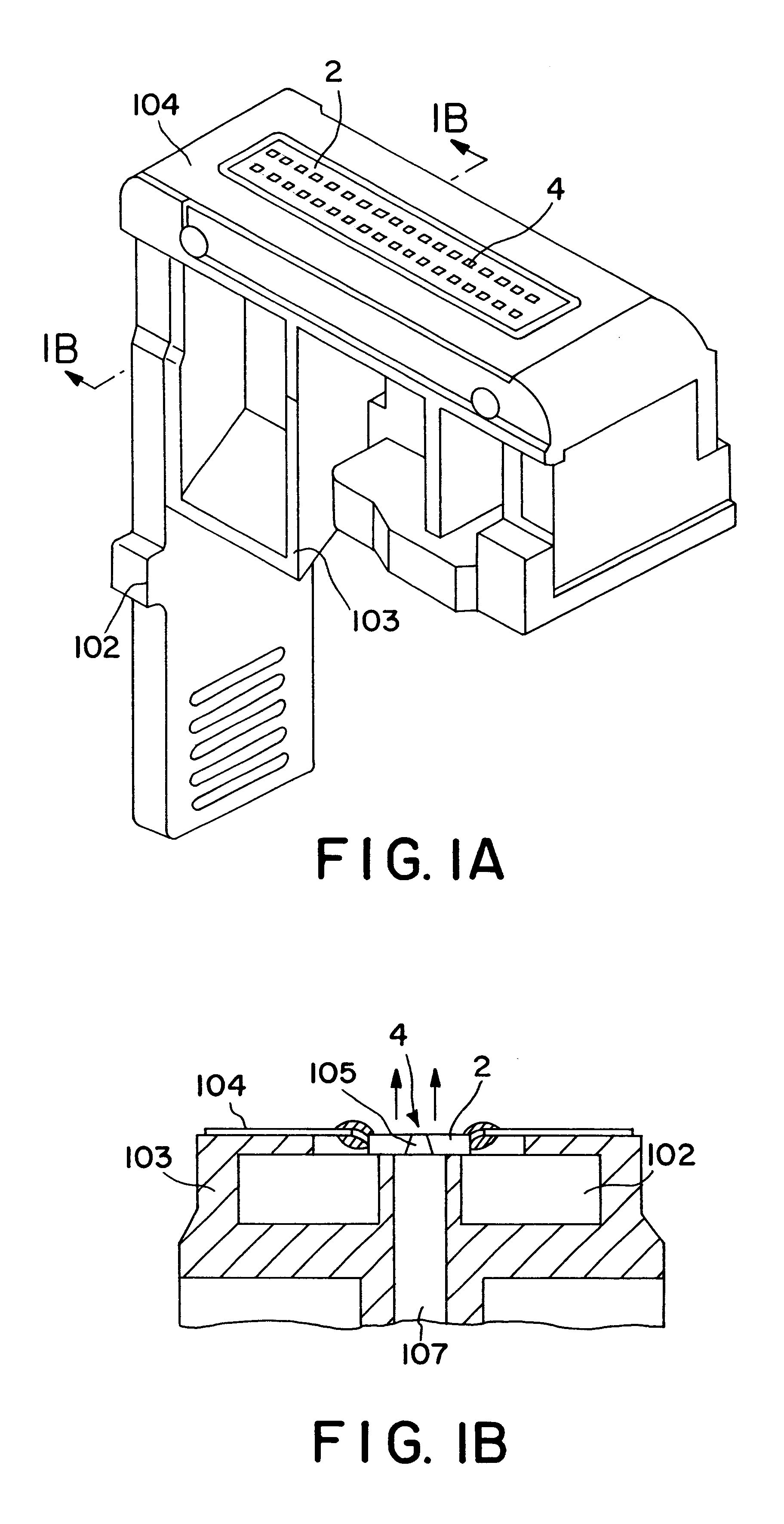
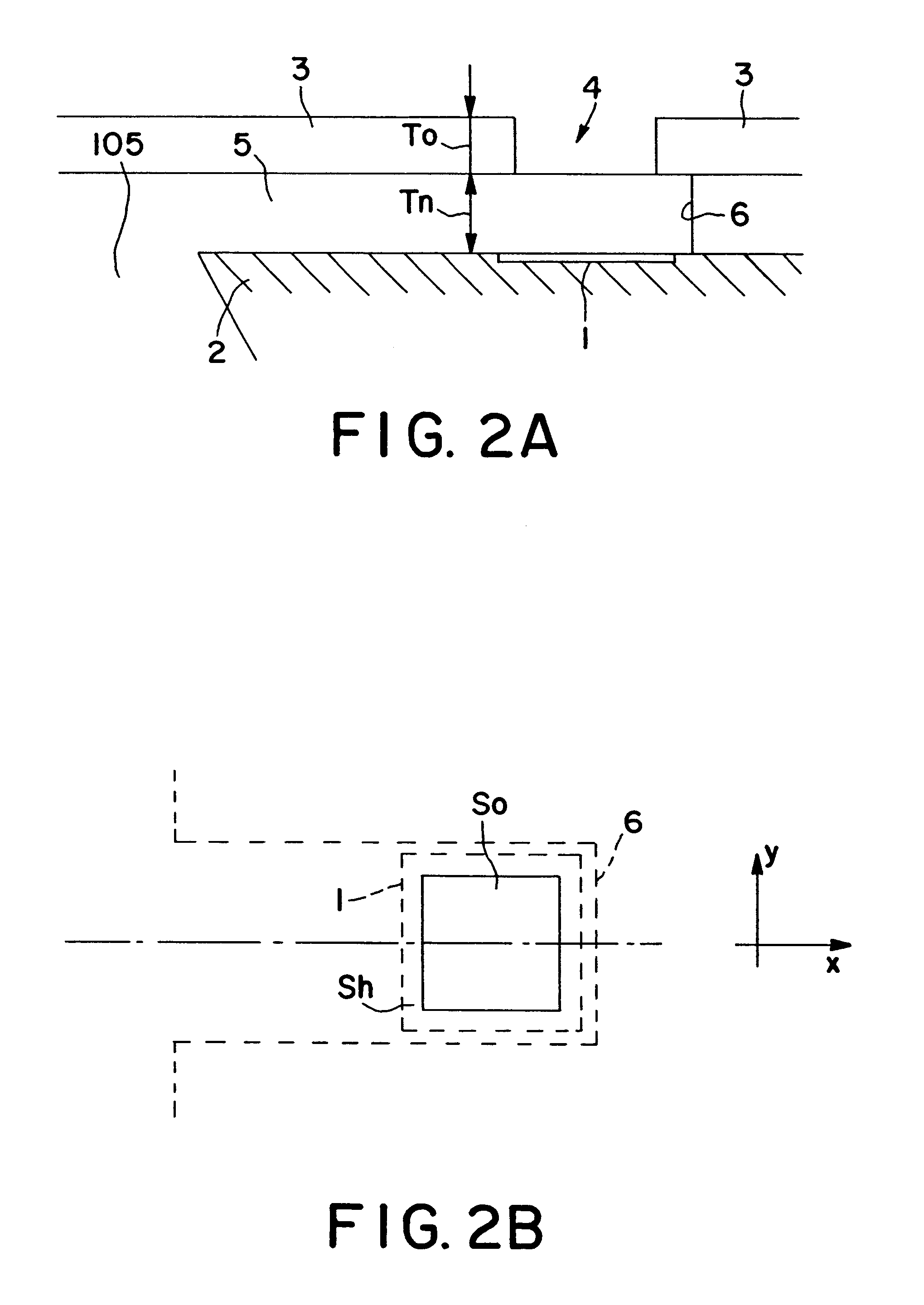
For the purpose of comparison, a liquid ejection head which had a structure similar to the one depicted in FIGS. 2A and 2B was produced, except for the dimensions of certain portions. In the comparative liquid ejection head, the thickness T.sub.0 of the orifice plate 3, which equals the distance from the ejection orifice 4 to the liquid path 5 was 9 .mu.m (T.sub.0 =9 .mu.m), and the height Tn of the liquid path 5 was 12 .mu.m (Tn=12 .mu.m). The pulse used to drive this comparative head was in the form of a single pulse which had a width of 2.9 .mu.sec, and a driving value of 9.72 V, or 1.2 times the ejection threshold voltage value of 2. The ink used to test the comparative head had the same properties as the ink used as the liquid described in the preceding embodiment.

Next, a conventional liquid ejection method will be described with reference to a liquid ejection head structured as described above.

FIGS. 4A-4G are sectional drawings which depict the liquid ejection sequence in a co...


PUM


Abstract

A liquid ejection method includes a step of preparing a liquid ejection head including an electrothermal transducer element for generating thermal energy contributable to ejection of liquid, an ejection outlet for ejecting the liquid, the ejection outlet being provided at a position opposed to the electrothermal transducer element, and a liquid flow path in fluid communication with the ejection outlet to supply the liquid to the ejection outlet and having the electrothermal transducer element on its bottom side; and a step of applying the thermal energy to the liquid to cause the liquid to undergo a change of state and thus to create a bubble. The liquid is ejected through the ejection outlet by the pressure of the bubble. The bubble is first in communication with ambience during reduction of the volume of the bubble after the bubble reaches a maximum volume.

Description

FIELD OF THE INVENTION AND RELATED ARTThe present invention relates to a method for ejecting liquid droplets onto various media, such as a sheet of paper, to record images on the medium. In particular, it relates to a method for ejecting extremely fine liquid droplets.There are various recording methods which have been put to practical use in various printers or similar apparatuses. Among them, the recording methods which employ the ink jet systems disclosed in the specifications of U.S. Pat. No. 4,723,129, and 4,740,796 are very effective. According to these patents, thermal energy is used to cause so-called "film boiling", and the bubbles generated by the "film-boiling" are used for ejecting liquid in the form of droplets.Among the ink jet based recording methods, the one disclosed in the specification of U.S. Pat. No. 4,410,899 has been known as an ink jet system based recording method of a sort that does not block a liquid path while forming a bubble.The inventions disclosed in ...

Claims


Application Information

Patent Timeline
IPC IPC(8): B41J2/14B41J2/05
CPCB41J2/1404B41J2002/14387B41J2002/14169B41J2/05
Inventor TACHIHARA, MASAYOSHIKANEKO, MINEO
Owner CANON KK
Why Eureka
Try Eureka