Automated laparoscopic lens cleaner

a technology of automatic cleaning and laparoscopic lens, which is applied in the field of apparatus and methods for cleaning and protecting the objective lens of a laparoscope, endoscope, or coeloscope, and can solve the problems of blood and other body fluids attaching to the lens, obscuring vision, and often soiled objective lens of the scop

Inactive Publication Date: 2002-03-12
KATO DANIEL T
View PDF11 Cites 238 Cited by
  • Summary
  • Abstract
  • Description
  • Claims
  • Application Information

AI Technical Summary

Problems solved by technology

Indeed, as longer and more complex surgical procedures are undertaken laparoscopically, laparoscopic surgeons rely on surgical techniques and novel laparasocopic instruments to facilitate laparoscopic surgery, reduce procedure time, and minimize the frustration which can be encountered when such techniques and instruments are not available.
The objective lens of the scope often becomes soiled during operative procedures.
Tissue particles, blood and other body fluids attach to the lens and obscure vision.

Method used


Image

  • Automated laparoscopic lens cleaner
  • Automated laparoscopic lens cleaner
  • Automated laparoscopic lens cleaner

Examples


Embodiment Construction

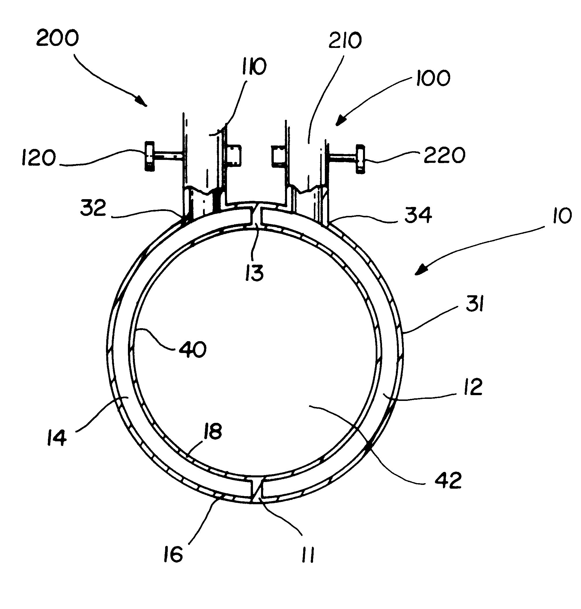
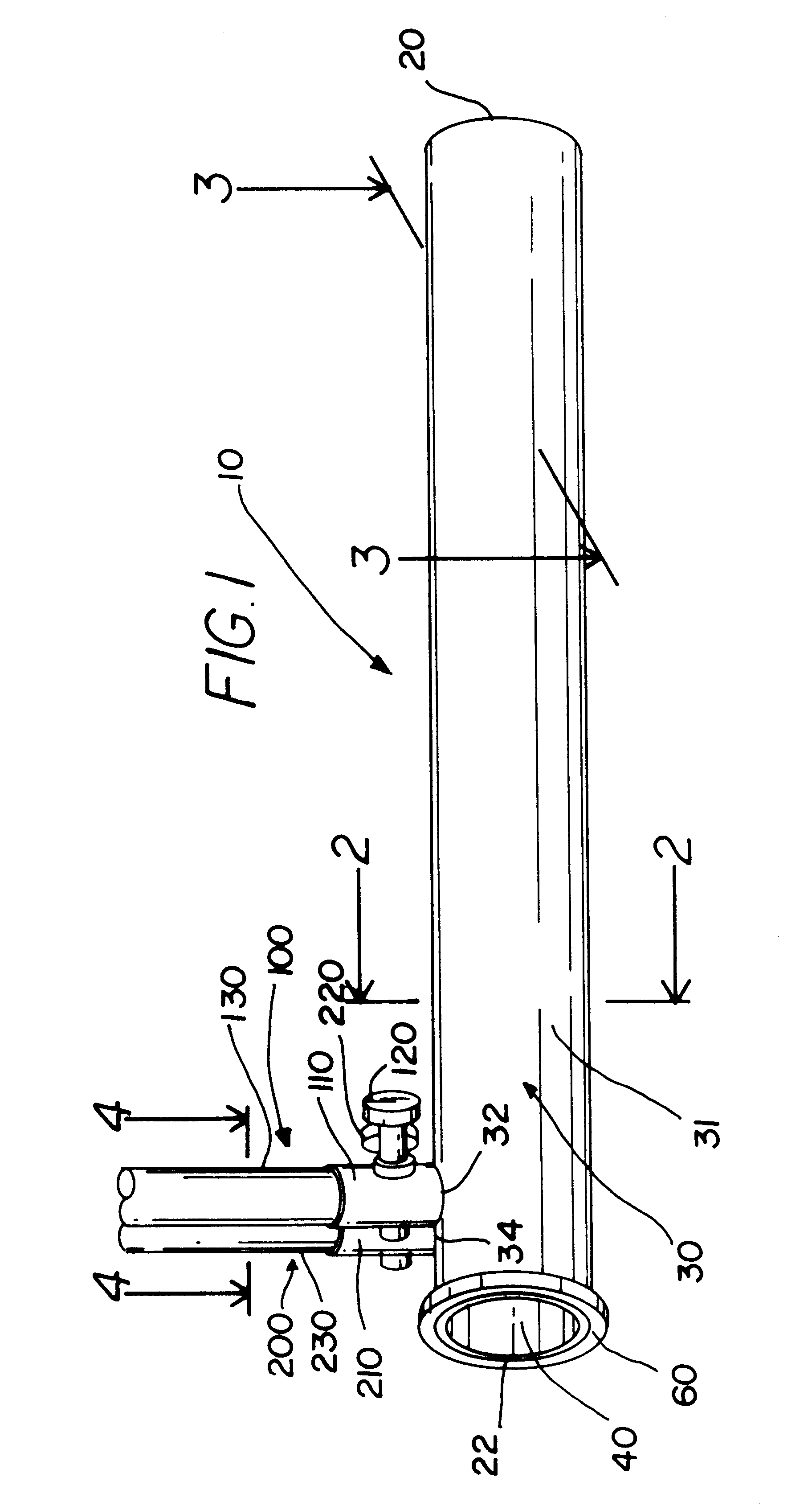
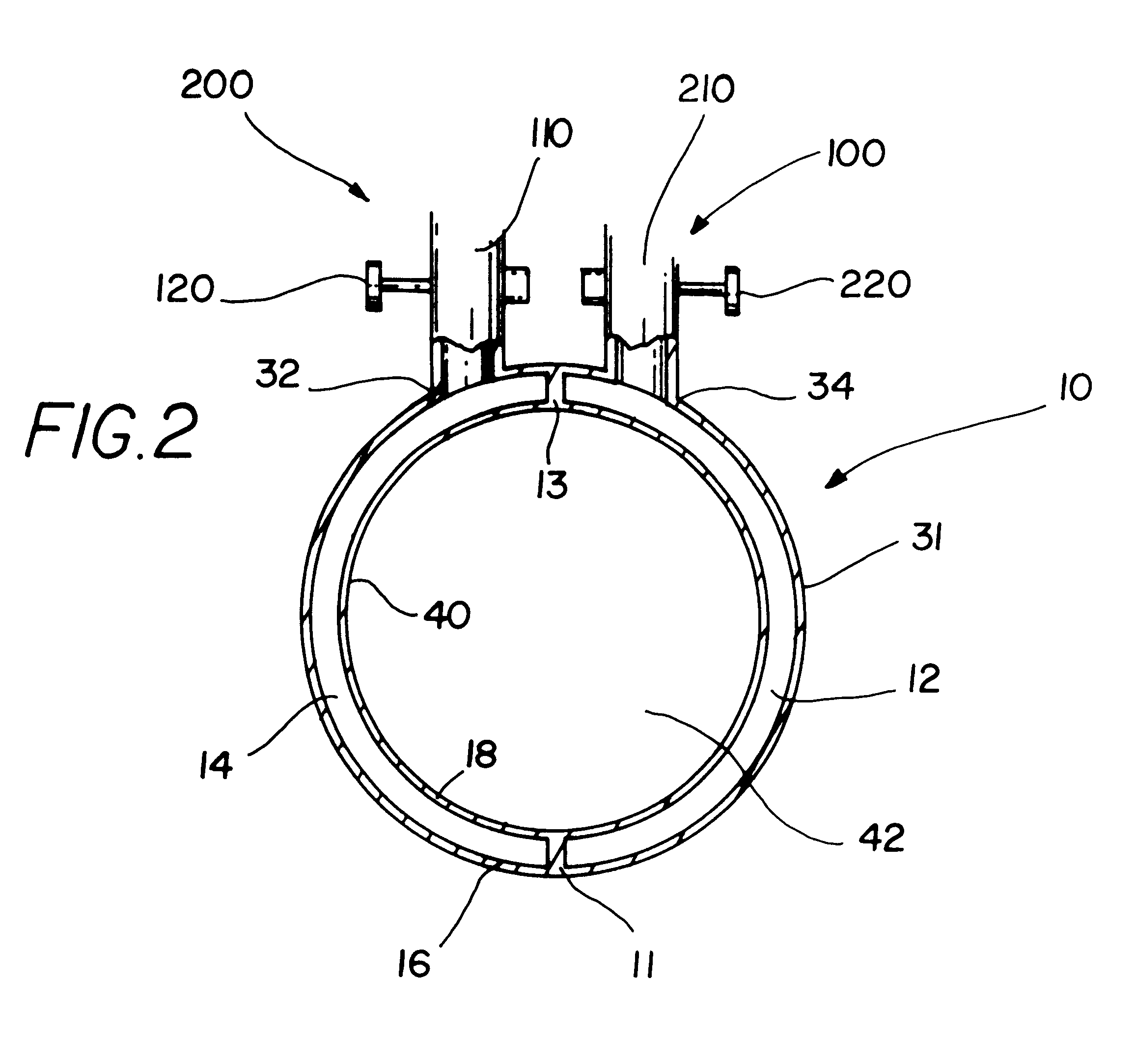
In FIG. 1, cleansing apparatus 10 is shown from a side perspective. Cleansing apparatus 10 has sheath 30, irrigation port 100 and suction port 200. Sheath 30 has patient end 20 and operator end 22. Operator end 22 of sheath 30 has ring 60 for tightening and sealing scope 300 (not shown in FIG. 1, see FIG. 3). Sheath 30 has outer surface 31 and inner surface 40. Irrigation port 100 has irrigation tubing 130, irrigation connector 110 and irrigation valve 120. Suction port 200 has suction tubing 230, suction connector 210 and suction valve 220. In FIG. 1, irrigation valve 120 and suction valve 220 are facing forward. The position of irrigation valve 120 and suction valve 220 can vary to meet the user's needs for comfort and accessibility. In the preferred embodiment, cleansing apparatus 10 is a disposable, one time use semi-automatic laparoscopic lens cleaning device fabricated from medical grade plastic. However, a laparoscope or other type of scope could be made in one piece employin...


PUM


Abstract

An apparatus and method for cleaning the objective lens of a laparoscope, endoscope, or coeloscope during surgery and also removing the solution and debris during and after the cleaning. The result is obtained by using a rigid hollow split sheath for the scope. The split sheath has two separate channels. One channel is for irrigation and the cleaning fluid flows through this channel to be directed onto the lens. The other channel is for suction to remove the solution and debris during and after the cleaning. Control buttons located at the operator's end activate the irrigation and suction functions. The control buttons for irrigation and suction are fabricated into an existing valve type device which can regulate either of these functions. In addition, two ports, one for irrigation and one for suction emerge from the operator's end to connect to the appropriate tubing for irrigation and suction. A rubber ring device screws down at the operator's end allowing the surgeon to secure the sheath to the scope and prevent any leakage of the standard carbon dioxide gas used to distend the abdomen for operative laparoscopy in the patient.

Description

1. Field of the InventionThe present invention relates to an apparatus and method for cleaning and protecting the objective lens of a laparoscope, endoscope, or coeloscope. In particular, the invention relates to an apparatus and method for cleaning and protecting the objective lens of the laparoscope, endoscope or coeloscope while the scope is in use within a body cavity through an irrigation channel and suction channel within the apparatus.2. Description of the Prior ArtMinimally invasive procedures, such as operative laparoscopy, have replaced simple and moderately complex surgical procedures that in the past have been done with large incisions, such as cholycystectomy, hysterectomy, and various gynecologic surgeries. Laparoscopic surgery is now recognized in most instances to substantially reduce patient care costs by decreasing post-operative patient discomfort and reducing hospitalization time. Ever more complex surgical procedures, such as intestinal resections, retroperitone...

Claims


Application Information

Patent Timeline
Patent Type & Authority Patents(United States)
IPC IPC(8): A61B1/12A61B19/00
CPCA61B1/121A61B1/126A61B2019/343A61B19/34A61B90/70A61B2090/701
Inventor KATO, DANIEL T.
Owner KATO DANIEL T
Why Eureka
Try Eureka