Microcomputer-controlled AC power switch controller and DC power supply method and apparatus

a microcomputer and power switch technology, applied in the direction of electric variable regulation, process and machine control, instruments, etc., can solve the problems of device on and off, not suited to dimming functionality,

Inactive Publication Date: 2002-03-12
BISHEL RICHARD A
View PDF12 Cites 176 Cited by
  • Summary
  • Abstract
  • Description
  • Claims
  • Application Information

AI Technical Summary

Benefits of technology

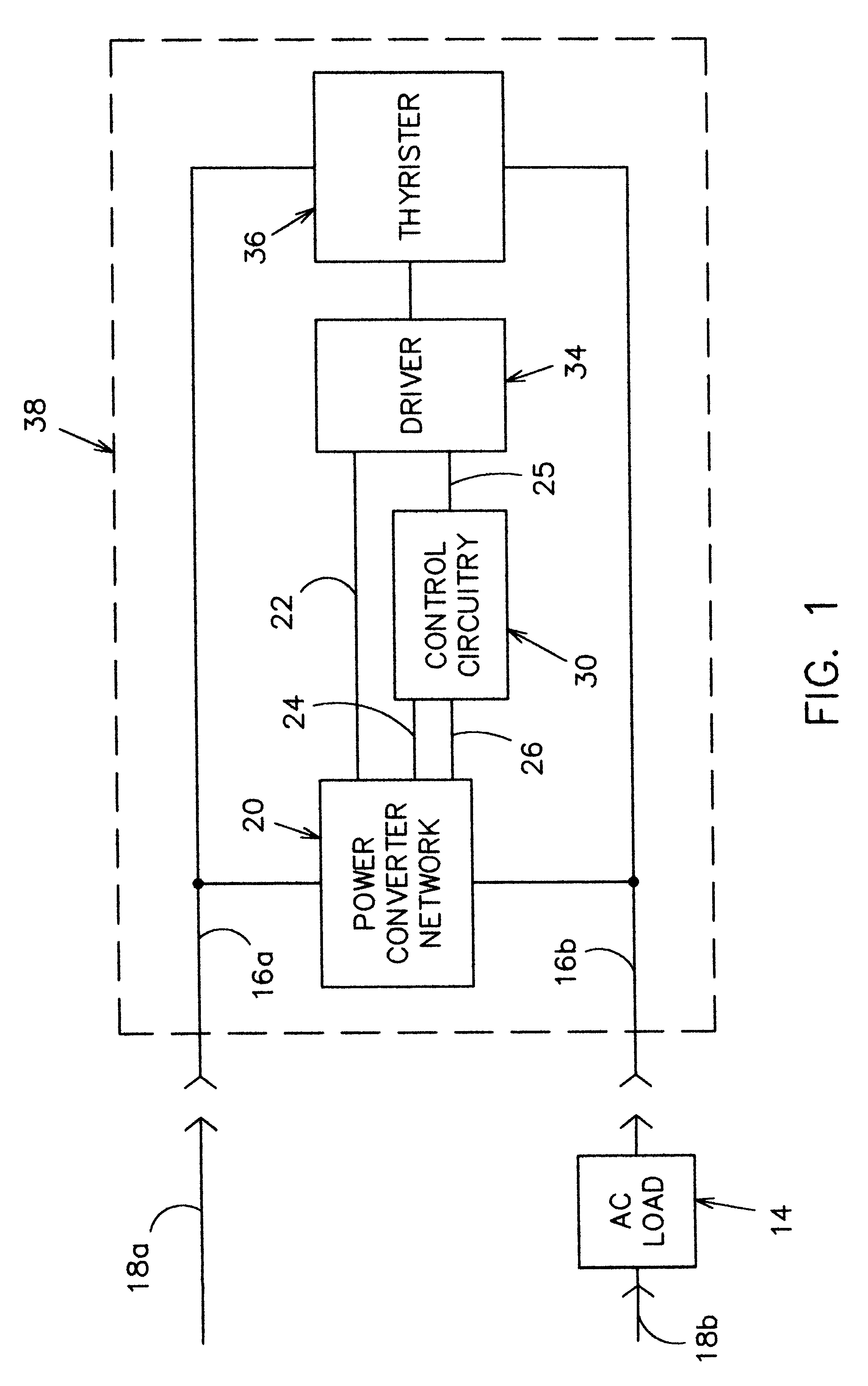
Since this design utilizes an isolation thyristor driver such as a relay or optoisolator driver, the microcontroller can easily be programmed to turn the power to the AC load ON and OFF, similar to if one were to use a controller with a dedicated power supply. The controller only needs to provide gate current pulse at the beginning of every halfcycle to enable the thyristor. Once the thyristor is provided with a gate current, it turns ON. The thyristor stays ON even without any further current in the gate until the AC voltage goes back to zero.
Another object of this invention is to provide a light controller which the light is turned ON and OFF at long random times from minutes to hours. This simulates that the house is lived in and deters burglars.
Another object of this invention is to provide a light controller, which has an attention-getting mode that flashes the light from full brightness to dim at a fast, periodic rate. This light controller if installed in the front porch light electrical circuit would help delivery personnel locate the house.

Problems solved by technology

The problem with these arrangements is that fixing the voltage where the thyristor turns ON limits the device to ON and OFF operations and does not lend itself to dimming functionality.

Method used


Image

  • Microcomputer-controlled AC power switch controller and DC power supply method and apparatus
  • Microcomputer-controlled AC power switch controller and DC power supply method and apparatus
  • Microcomputer-controlled AC power switch controller and DC power supply method and apparatus

Examples


second embodiment

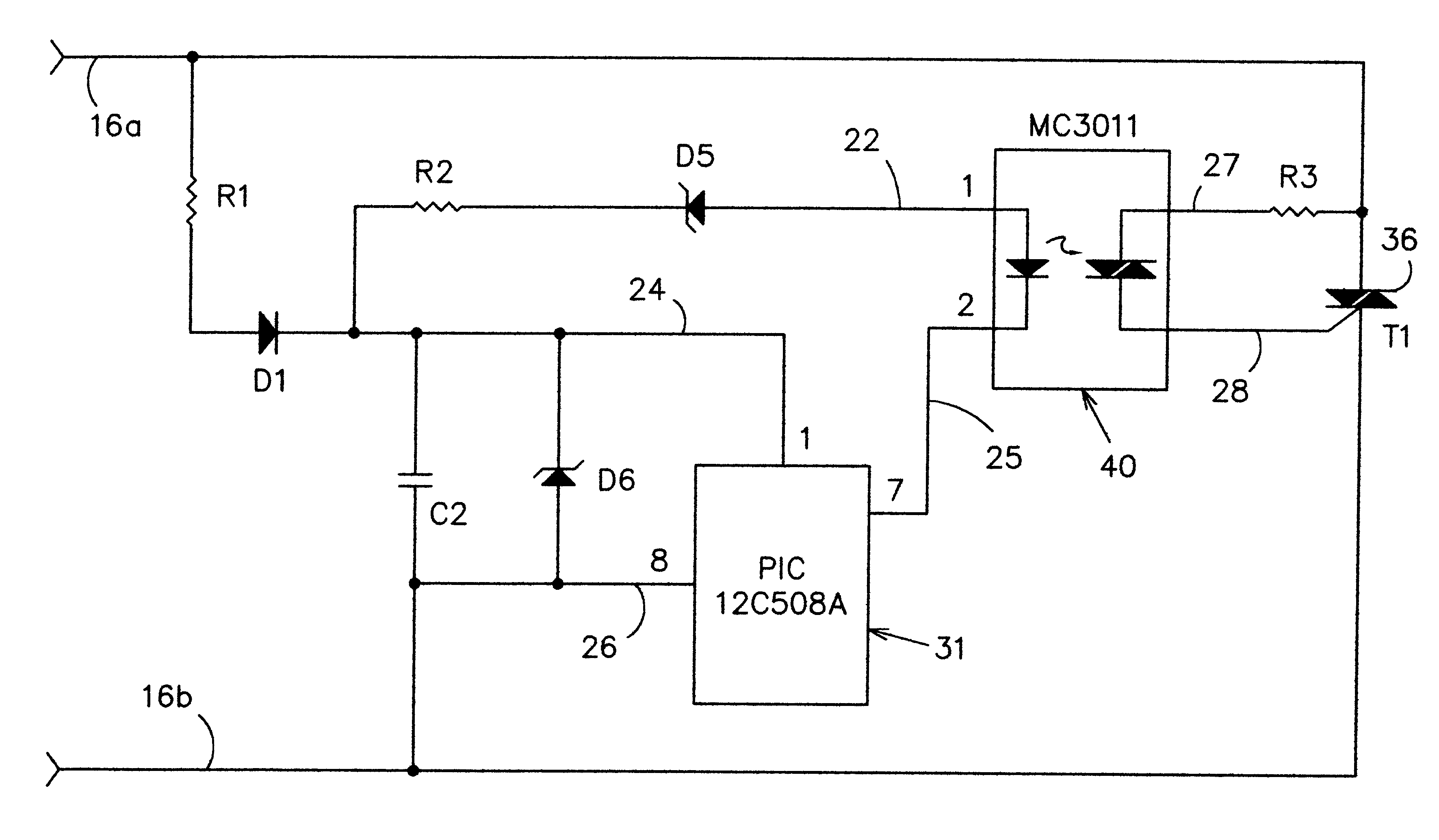
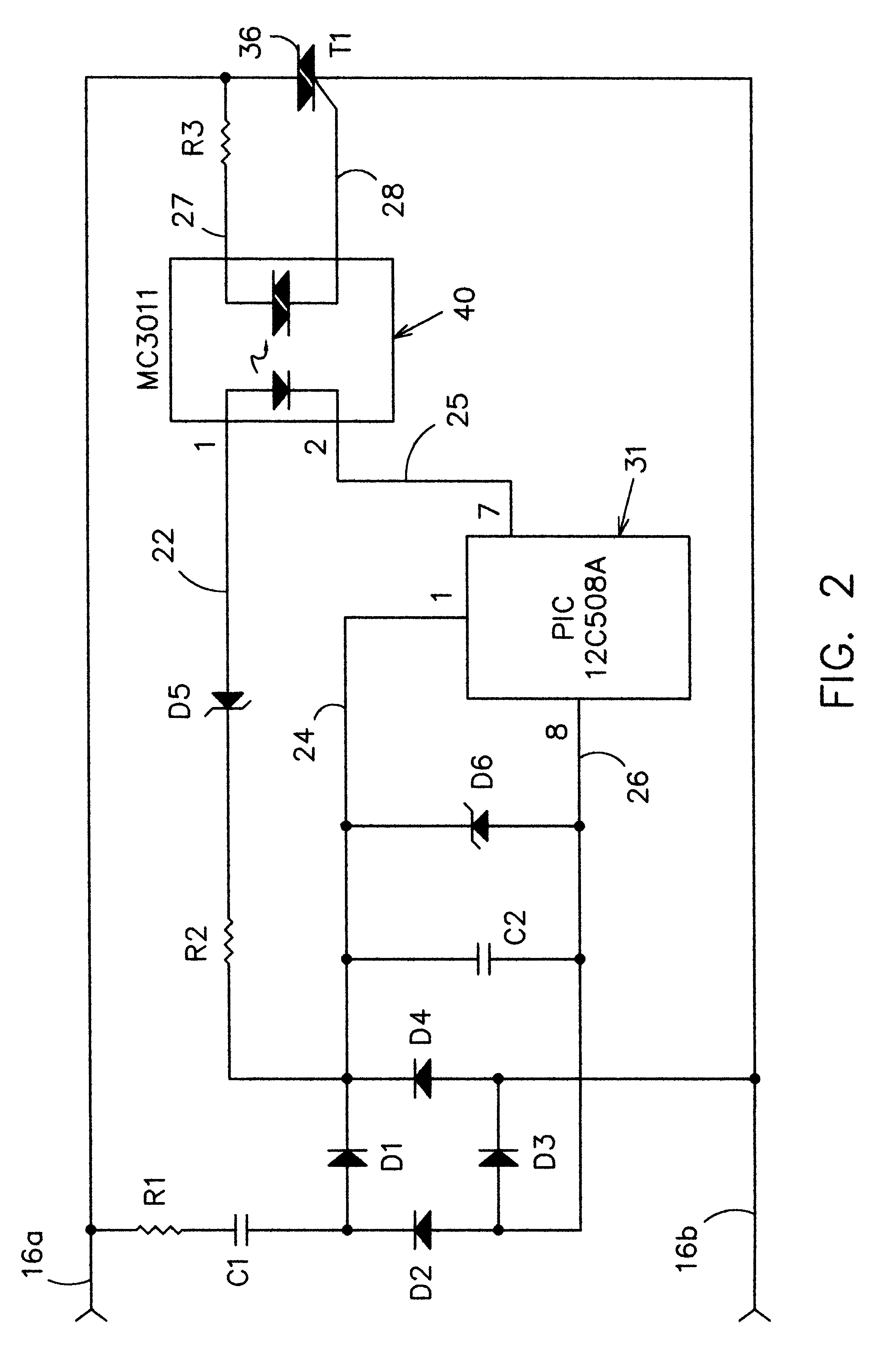
FIG. 4 shows a second embodiment, where the power conversion network includes resistor R1 and diode D1 instead of R1, C1, and diodes D1-D4. Here, the resistor R1 has a larger power rating to handle the current flow needed for the microcontroller 31 and thyristor driver 40. In order to minimize the current, this circuit uses a thyristor driver 40 with a more sensitive internal LED such as the Motorola MC3012. Diode D1 only provides power on every positive-going AC cycle.

third embodiment

FIG. 5 shows third embodiment where the electrical circuit uses a capacitor C1 and a smaller value for R1 to provide the needed power. Diode D2 is needed for allowing the AC voltage to charge and discharge capacitor C1. The DC power is derived from the AC power only on positive going AC cycles.

d. Thyristor Driver

FIG. 6 illustrates another embodiment of the device using a relay 41 such as 12 VDC reed relay, Radio-Shack No. 275-233, instead of an optoisolator driver 40 in the circuitry. D5 is not needed because R2 and the resistance of the relay coil is large enough to minimize loading of the power network.

FIG. 7 illustrates another embodiment of the device using an optoisolator driver 40 with only a higher value resistor R2. With this circuitry, the AC voltage across leads 16a and 16b will be much higher to produce the necessary drive current for the optoisolator driver 40. To minimize the drive current, a more sensitive optoisolator driver such as Motorola MC3012 would be used.

FIG. ...


PUM


Abstract

An AC controller which provides programmable switching of AC power flow, together with producing a source of DC power for operating the AC controller. The AC controller is connected in series with only one side of the AC power source and the AC load. The AC controller utilizes a thyristor for AC power control switching. During the operation, the AC controller steals a small portion of each half-cycle of the AC power to provide DC power to the AC controller. The AC controller enables the flow of AC current by providing a gate current pulse at any predetermined time during the half cycle. Once the thyristor is ON, the AC current flows through the thyristor until the AC cycle is at or near zero. To provide an OFF state, the AC controller does not provide a gate current pulse. The AC controller uses an microcontroller for the programmable capability. The AC controller can be programmed to provide a flashing light function, a time delay off mode, an automatic fade mode, a dimming function, a burglar deterrent function, and a time delay dim function. With a three-position switch which can replace existing types of wall switches, three modes of operation are achieved: ON, OFF, and MODE. The mode position initiates operation of the special function of the controller.

Description

This invention relates to AC electric current control systems, such as motor controllers and illumination switches.The connection of AC power controllers with the wiring of buildings is usually obtainable only with one side of the AC power line. For example, the wire for the switch circuit from a ceiling or porch light is often connected with the hot side of the AC circuit being the only line switched. Therefore, full line power is not available at most wall switch locations. As a result of this wiring practice, it is necessary that any electrical device intended to find popular acceptance as a replacement for a wall-mounted switch must rely upon merely the power present in the one side of the circuit. Such a device must be connected in series with the load and the AC power source.Also, wall-mounted switch controllers which include dimmers, time-delay devices, emergency flashing devices, variable intensity controllers, and motor controllers are designed as dedicated devices that ser...

Claims


Application Information

Patent Timeline
Patent Type & Authority Patents(United States)
IPC IPC(8): H04M11/04H04M11/00
CPCH04M11/007H04M11/04Y10S323/905
Inventor BISHEL, RICHARD A.
Owner BISHEL RICHARD A
Why Eureka
Try Eureka