Mems variable optical delay lines

a variable optical delay and delay line technology, applied in the field of micro electromechanical systems (mems) devices, can solve the problems of propagation delay, path delay, and path delay changes (in small amounts)

Inactive Publication Date: 2002-03-12
LUCENT TECH INC
View PDF6 Cites 30 Cited by
  • Summary
  • Abstract
  • Description
  • Claims
  • Application Information

AI Technical Summary

Benefits of technology

It is therefore an object of the present invention to provide a MEMS variable optica

Problems solved by technology

As the bit speeds at which data and information are transferred increases in optical systems such as these, so does the propagation delay.
Even in systems having fixed delay elements, the path delay changes (in small amounts).
This path delay can be caused, for exampl

Method used


Image

  • Mems variable optical delay lines
  • Mems variable optical delay lines
  • Mems variable optical delay lines

Examples


Embodiment Construction

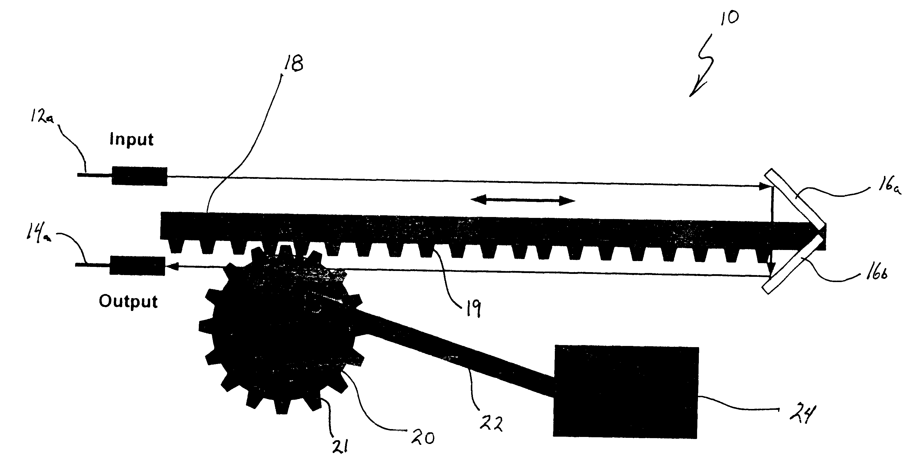
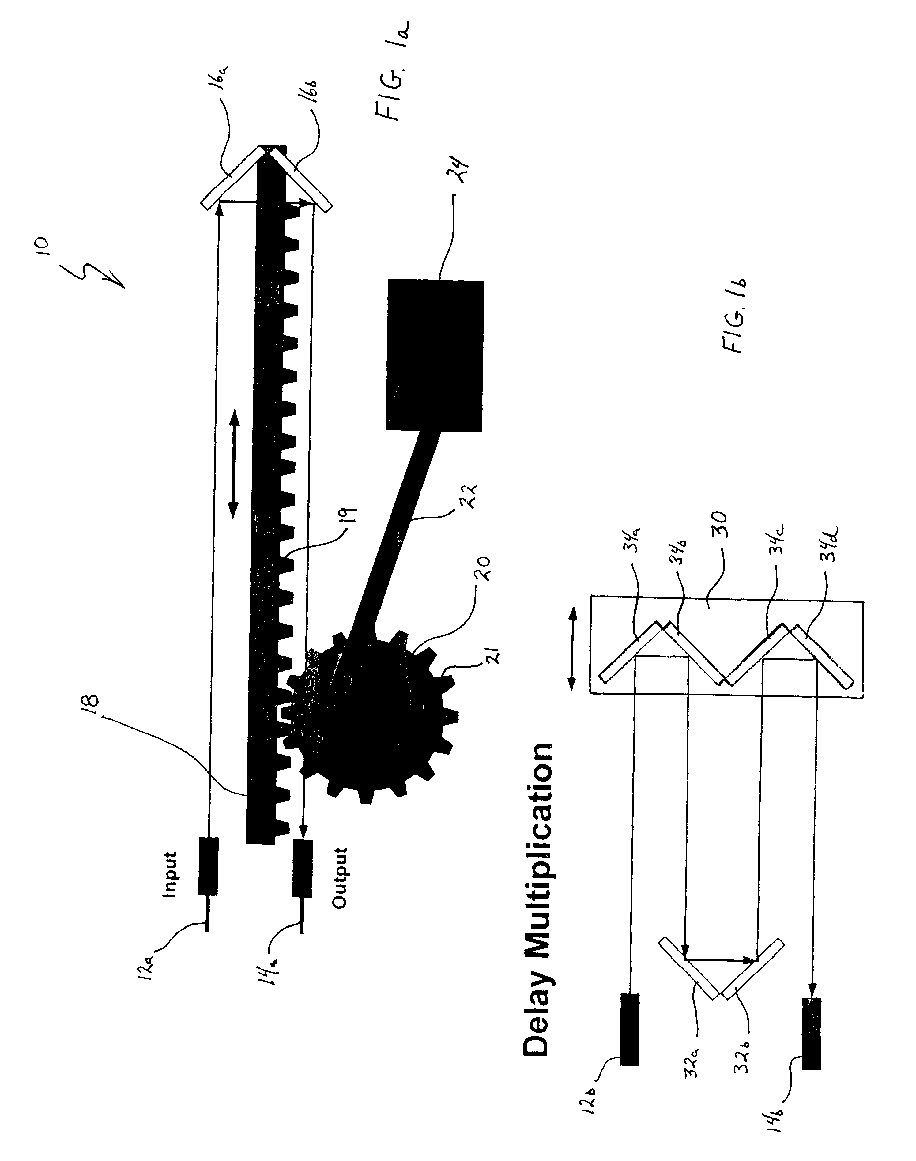
FIG. 1a shows a MEMS variable optical delay line 10 having an input waveguide or fiber 12a and an output waveguide or fiber 14a. A micro retroreflector defined by two mirrors 16a and 16b are arranged on a micro machine linear rack 18 so that the light wave transmitted from input 12a is reflected back into output 14a. The micro machine linear rack 18 can be, for example, a silicon micro machine linear rack which is operatively capable of several millimeters of travel.

The micro machine linear rack includes gears 19 which mesh with the gears 21 of a drive gear 20. Drive gear 20 is rotatively driven by a drive arm 22 connected to a drive motor 24. Drive motor 24 is preferably connected to a computer controller (not shown) which provides control signals to the motor to effect desired movement of linear rack 18 and thereby variably control the length of the signal path between the input 12a and output 14a. Such selective variation of the distance between the micro machine retroreflector f...


PUM


Abstract

A variable optical delay line using MEMS devices. A reflector on a micro machine linear rack is positioned and spaced from an input source and/or an output to receive and reflect input light waves toward the output. The distance between the reflector and the input and output is variable and thereby enables selective path delay compensation of the input light wave signals. Other disclosed embodiments utilize pivoting MEMS mirrors and selective adjustment of the mirror pivot angles to provide the selective path delay compensation required in a light wave system.

Description

BACKGROUND OF THE INVENTION1. Field of the InventionThe present invention relates to micro electromechanical systems (MEMS) devices and, more particularly, to a MEMS apparatus that compensates for signal path delay in optical systems.2. Description of the Related ArtAdvanced optical (light wave) systems generally include some sort of compensation in the transmitting and / or receiving of information through optical lines. Some examples of this are compensation of polarization mode dispersion (PMD) and optical pulse timing in wavelength-division multiplexed and optically time-division multiplexed (OTDM) transmitters. In such applications, small adjustments (equivalent to several bit periods in PMD compensators and a single bit-period in OTDM transmitters) in the optical path lengths are needed in order to compensate for signal path delay. For example, in a 40 Gb / s data rate system, the 25 ps bit period has a corresponding free space bit length of cT=7.5 mm.As the bit speeds at which da...

Claims


Application Information

Patent Timeline
IPC IPC(8): G02B6/28G02B26/06B81B5/00
CPCG02B6/2861G02B17/023
Inventor BISHOP, DAVID JOHNGILES, RANDY CLINTON
Owner LUCENT TECH INC
Why Eureka
Try Eureka