
Unitized boot seal for ball joints

a unitized and ball joint technology, applied in the direction of mechanical equipment, couplings, transportation and packaging, etc., can solve the problems of ball joint wear, aforementioned wear and the formation of an opening in the boot, and wear to the joint connection

Inactive Publication Date: 2002-03-19
DANA HEAVY VEHICLE SYSTEMS GROUP LLC
View PDF21 Cites 44 Cited by
  • Summary
  • Abstract
  • Description
  • Claims
  • Application Information

AI Technical Summary

Benefits of technology

It is a further object according to the present invention to provide a secondary sealing portion for the boot seal of the tie rod end ball joint that is both manufacturing friendly and cost effective.

Problems solved by technology

After a period of time, the ball joint may be subject to wear as a result of contact by one or both members.
This is especially true if the ball joint is surrounded by a rubber boot seal that is continually abraded by a mating member during motion, thereby resulting in the aforementioned wear and the formation of an opening in the boot.
When this wear occurs in the boot seal, contamination in the form of water, dust and road salt may enter the opening causing wear to the joint connection.
Moreover, the interface between the boot and the ball joint members tends to become separated from the member(s) during prolonged use, and it is common for contamination to intrude upon the sealed area after such prolonged use.
Again, the aforementioned wear is a result of abrasion by the tie rod arm of the steering knuckle against the ball joint and boot seal during articulation.
Moreover, the boot tends to separate from the ball joint shaft during use, and contamination enters the sealed area as a result of such separation.
However, these conventional devices do not effectively protect the boot seal from damage or divert contamination away from the boot to shaft interface.
Existing tie rod assembly designs do not adequately prevent contamination at the rotating boot to arm boss interface and the boot to ball stud.
The surface of the steering knuckle is forged or rough machined, and such rough machine surface finish provide an inadequate surface for the seal interface to seal against contamination entry into the tie rod end.
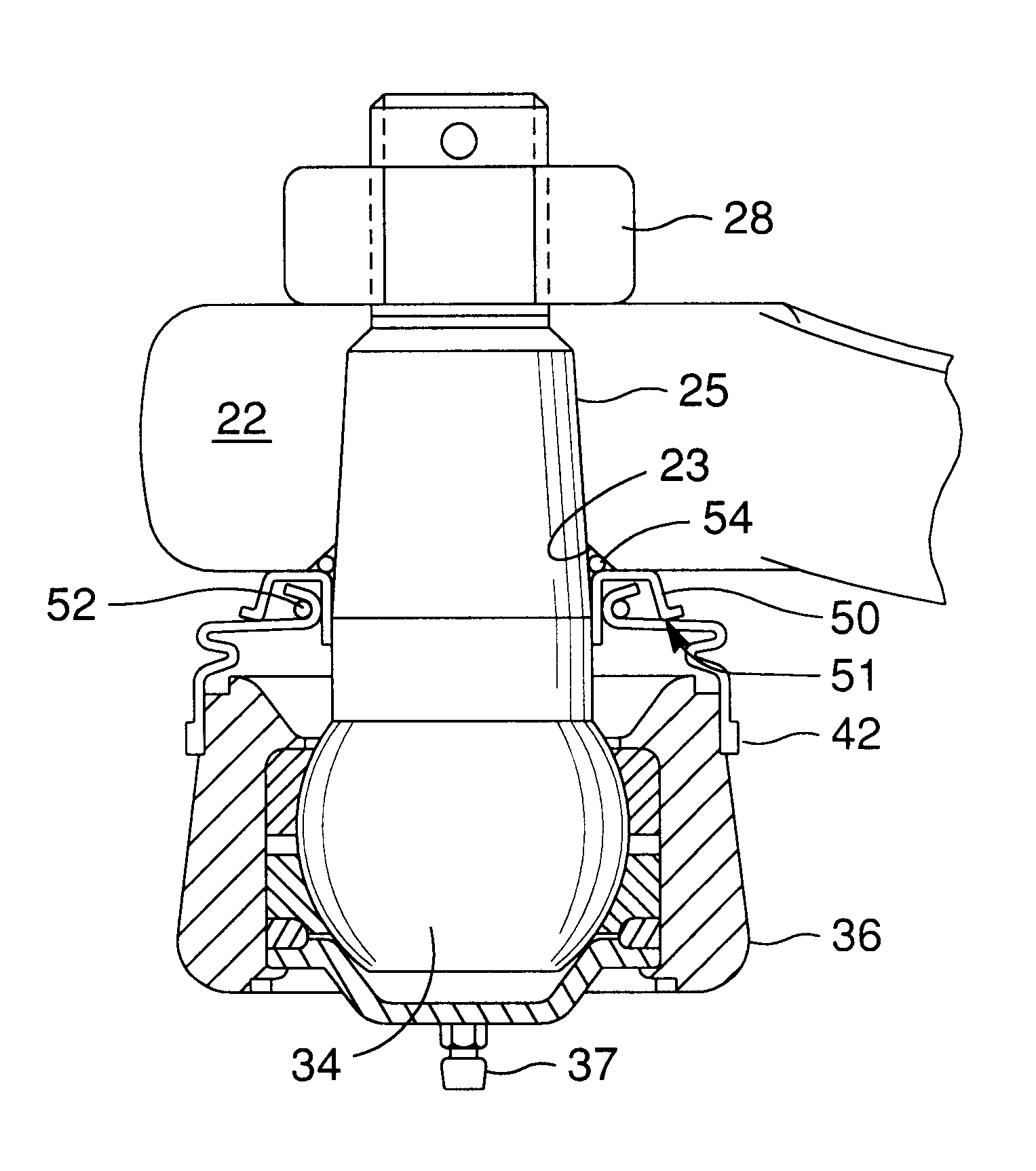
The formed seal provides a labyrinth that makes it difficult for contamination to reach the boot seal / ball stud interface.

Method used


Image

  • Unitized boot seal for ball joints
  • Unitized boot seal for ball joints
  • Unitized boot seal for ball joints

Examples


Embodiment Construction

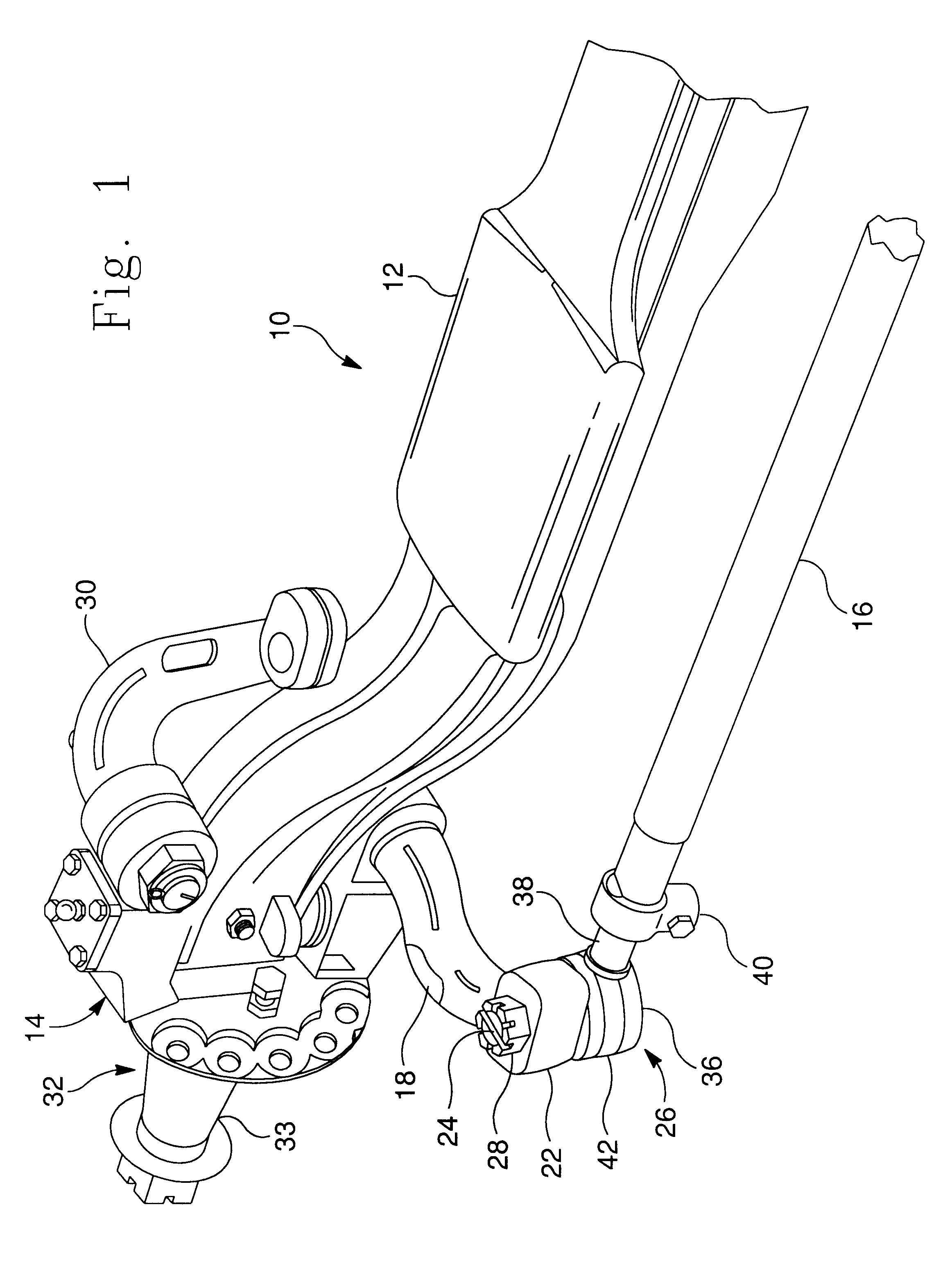
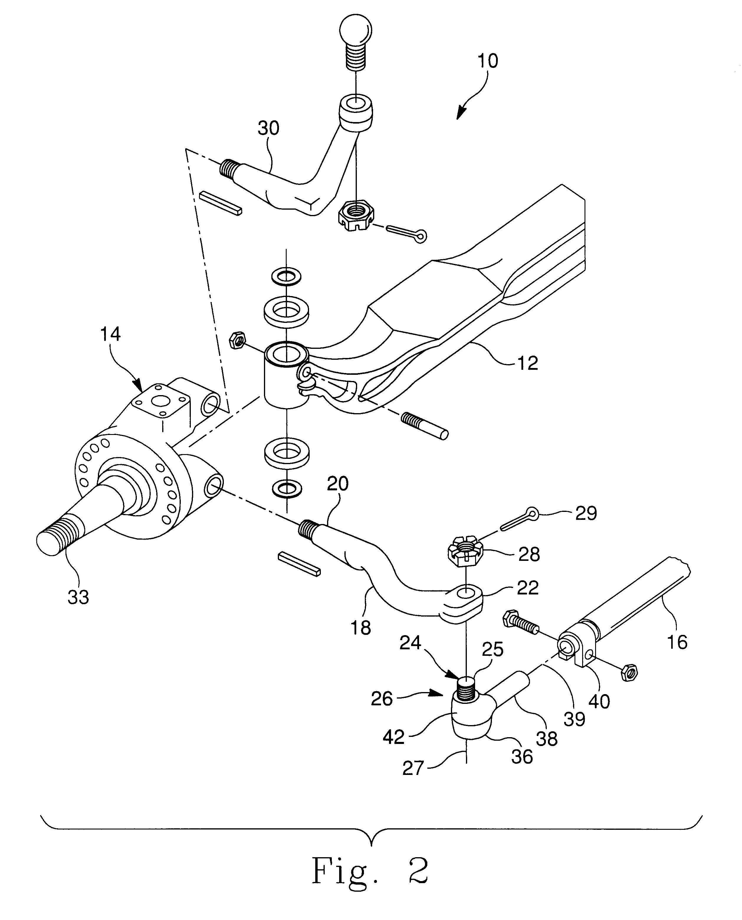
With reference to FIG. 1 of the drawings, shown is a partial perspective view of a typical front steering assembly 10 of a motor vehicle. Included in front steering assembly 10 are major components and sub-assemblies such as a steer axle beam 12, a steering knuckle 14, and a tie rod (or track rod) cross tube 16. Steer axle beam 12 is received by steering knuckle 14 and is coupled thereto. These components are also shown in FIG. 2.

Steering knuckle assembly 14 includes an input / output member 18 which is more commonly known as a tie rod arm (or Ackermann Arm). Tie rod arm 18 has a first end 20 which is coupled to steering knuckle assembly 14 and a second end 22 which is affixed to a ball stud 24 of a ball joint assembly 26, and mounted thereto by a nut 28. Of course, tie rod arm 18 may also be formed integral to steering knuckle assembly 14. More particularly, the second end 22 (boss end) of tie rod arm 18 is affixed to shank portion 25 of ball stud 24. Steering knuckle assembly 14 als...


PUM


Abstract

A pivotal ball joint assembly includes a ball joint, an input / output member, and a sealing element to provide a sealing surface abutting the boot seal and to prevent contamination of the boot seal during movement and articulation of the input / output member relative to the ball joint. The ball joint has a socket body and a ball stud pivotally mounted to the socket body. The ball stud has a shank portion that extends therefrom and is aligned along a shank axis. An elastic boot seal that extends between the ball stud and socket body is also included. The pivotal ball joint assembly also includes an input / output member affixed to the ball stud shank portion so that the socket body is able to freely rotate relative to the input / output shaft about the shank axis. The pivotal ball joint assembly is further rotatable through a limited range about a transverse axis perpendicular to the shank axis. The seal element is interposed between the boot seal, the shank portion and the input / output member to enhance the boot seal interface and thereby guard the boot seal to shank portion interface against contamination during movement and articulation of the input / output member relative to the ball joint.

Description

a) Field of the InventionThe present invention pertains generally to a ball joint for motor vehicles, and more particularly to a unitized boot seal formed of an elastically deformable material in which a metallic sealing element is provided adjacent the boot seal to shaft interface to prevent contamination of the sealed area.b) Description of Related ArtBall joints are commonly used as a pivotal coupling for allowing two members to angularly move with respect to each other. After a period of time, the ball joint may be subject to wear as a result of contact by one or both members. This is especially true if the ball joint is surrounded by a rubber boot seal that is continually abraded by a mating member during motion, thereby resulting in the aforementioned wear and the formation of an opening in the boot. When this wear occurs in the boot seal, contamination in the form of water, dust and road salt may enter the opening causing wear to the joint connection. Moreover, the interface ...

Claims


Application Information

Patent Timeline
Patent Type & Authority Patents(United States)
IPC IPC(8): F16C11/06
CPCB60G7/005B62D7/166F16C11/0671F16J3/042B60G2200/30B60G2200/44B60G2204/416B60G2204/43B60G2206/11Y10T403/32729B60G2206/50B60G2206/8207B60G2206/31F16C2326/24F16C2326/05
Inventor ZEBOLSKY, MICHAEL L.DAVIS, MARK A.MOSES, DAVID G.
Owner DANA HEAVY VEHICLE SYSTEMS GROUP LLC
Learn More