
Direct electrostatic printing method and apparatus

Inactive Publication Date: 2002-03-26
ARRAY PRINTERS PUBL
View PDF123 Cites 2 Cited by
  • Summary
  • Abstract
  • Description
  • Claims
  • Application Information

AI Technical Summary

Benefits of technology

Yet a further object of the present invention is to provide a method of and a device for decreasing the need for an extremely high mechanical precision during manufacturing of printers working according to direct electrostatic printing methods.
Another object of the present invention is to provide a method of and device for reducing or eliminating perceived uneven image density in direct electrostatic printing methods.
Yet another object of the present invention is to provide a method of and a device for for reducing or eliminating perceived uneven image density in direct electrostatic printing methods due to mechanical imperfections.
Yet another object of the present invention is to provide a method of and a device for for reducing or eliminating the influence of distance variations between a printhead structure and a pigment source due to mechanical imperfections.

Problems solved by technology

Thus, the transversal print addressability is limited by the density of apertures through the printhead structure.
However, it can be considered a drawback of current direct electrostatic printing methods that sometimes when printing an image the perceived image density of individual apertures varies over time for the same desired image density.
It can also be considered a drawback of current direct electrostatic printing methods that the mechanical precision of interrelating parts of the printer has to be very high.

Method used


Image

  • Direct electrostatic printing method and apparatus
  • Direct electrostatic printing method and apparatus
  • Direct electrostatic printing method and apparatus

Examples


Embodiment Construction

In order to clarify the method and device according to the invention, some examples of its use will now be described in connection with FIGS. 1 to 13.

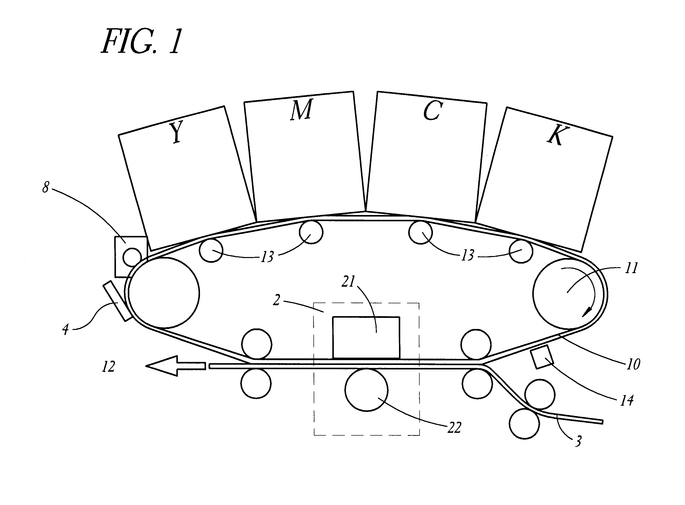
FIG. 1 is a schematic section view of an image recording apparatus according to a first embodiment of the invention, comprising at least one print station, preferably four print stations (Y, M, C, K), an intermediate image receiving member, a driving roller 11, at least one support roller 12, and preferably several adjustable holding elements 13. The four print stations (Y, M, C, K) are arranged in relation to the intermediate image receiving member. The intermediate image receiving member, preferably a transfer belt 10, is mounted over the driving roller 11. The at least one support roller 12 is provided with a mechanism for maintaining the transfer belt 10 with at least a constant surface tension, while preventing transversal movement of the transfer belt 10. The preferably several adjustable holding elements 13 are for accurately po...


PUM


Abstract

A direct electrostatic printing device and method print an image to an information carrier with increased density during printing. This is attained by measuring undesired image density variations in a direction parallel to the relative movement between an image receiving member and a printhead structure. The density variations are caused by distance variations between the printhead structure and a pigment particle source during printing, which at least in part is caused by a relative movement between at least a part of the pigment particle source and the printhead structure. A control unit is arranged to control the transport of pigment particles in such a way as to compensate for these undesired image density variations during printing, thus attaining a percepted uniform image density along a printed image for a specific desired image density.

Description

The present invention relates to direct electrostatic printing methods in which charged toner particles are transported under control from a particle source in accordance with an image information to form a toner image used in a copier, a printer, a plotter, a facsimile, or the like.BACKGROUND TO THE INVENTIONAccording to a direct electrostatic printing method, such as that disclosed in U.S. Pat. No. 5,036,341, a background electric field is produced between a developer sleeve and a back electrode to enable the transport of charged toner particles therebetween. A printhead structure, such as an electrode matrix provided with a plurality of selectable apertures, is interposed in the background electric field and connected to a control unit which converts an image information into a pattern of electrostatic control fields which selectively open or close the apertures, thereby permitting or restricting the transport of toner particles from the developer sleeve. The modulated stream of ...

Claims


Application Information

Patent Timeline
IPC IPC(8): B41J2/41B41J2/415G03G15/00G03G15/34B41J2/385G03G15/05
CPCB41J2/4155G03G15/346G03G2217/0025
Inventor JONSSON, TOMAS
Owner ARRAY PRINTERS PUBL
Learn More