
Pinion support

a pinion and pinion technology, applied in the field of pinion pinion support, can solve the problems of unsatisfactory system oscillation, affecting the operation of the motor/gear box, and flexing of the pinion away from the load, so as to prevent oscillation and vibration of the motor, and eliminate the flexing of the pinion

Inactive Publication Date: 2002-04-02
VALIANT CO LTD
View PDF5 Cites 6 Cited by
  • Summary
  • Abstract
  • Description
  • Claims
  • Application Information

AI Technical Summary

Benefits of technology

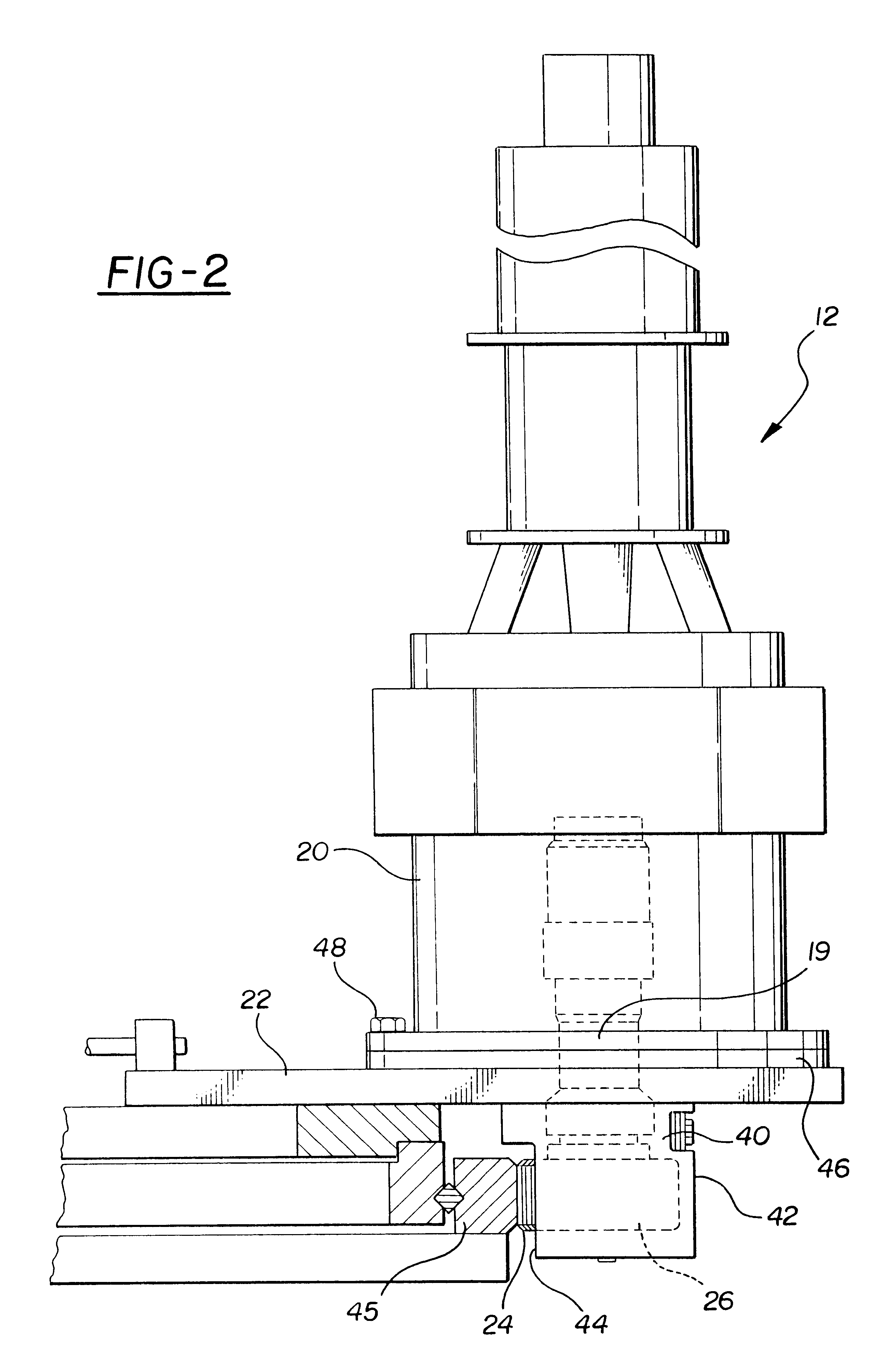
A cylindrical pin is rigidly fixed to the end plate and extends coaxially into an axial recess formed on the outer end of the pinion. A bearing assembly is operatively disclosed between the pin and the pinion recess and, preferably, a seal is provided between the pin and pinion recess to protect the bearing assembly from debris.
In operation, the rotational support provided between the pin and the bearing assembly and the outer or free end of the pinion operates to support the pinion and preclude flexing of the pinion relative to the housing and thus relative to the gear box casing. In practice, such support not only eliminates flexing of the pinion during operation and radial load on output bearing, but also prevents oscillation and vibration of the motor which can otherwise occur especially in case of speed or torque closed loop control, with heavy inertia.

Problems solved by technology

In many such applications, however, the pinion is subjected to high torque which may result in slight flexing of the pinion away from the load.
Any such flexing not only results in unsatisfactory oscillation of the system, but can also result in inaccurate positioning of the load driven by the motor / gear box, and in some case in shaft breaking by fatigue.

Method used


Image

  • Pinion support
  • Pinion support
  • Pinion support

Examples


Embodiment Construction

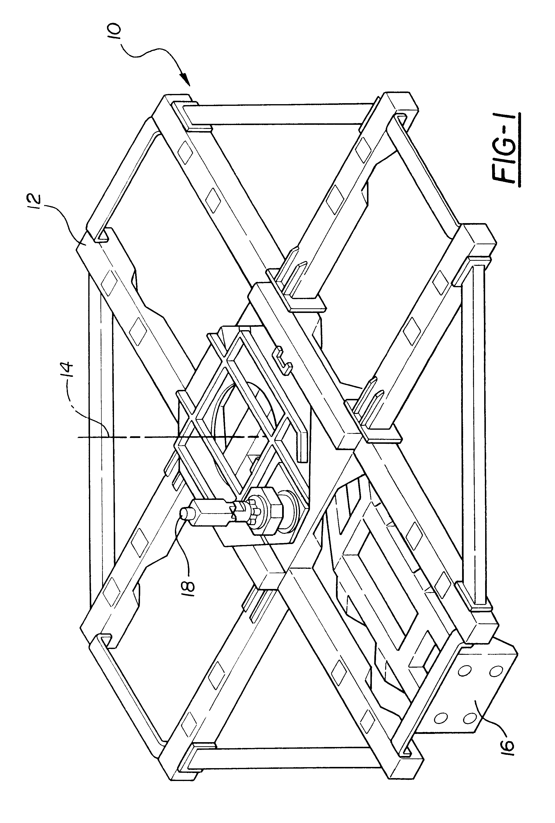
With reference to FIG. 1, a portion of an automotive framing system 10 is there shown having a turret 12 which is rotatable about a generally vertical axis 14. In the well known fashion, tooling 16 is supported by the turret 12 to selectively clamp an automotive body (not shown) prior to welding.

The automotive framing system 10 typically accommodates several different models of vehicles, each vehicle having its own set of tooling 16. In order to position the tooling 16 at the work station, a motor 18 is selectively actuated to rotatably index the turret 12 about the vertical axis 14.

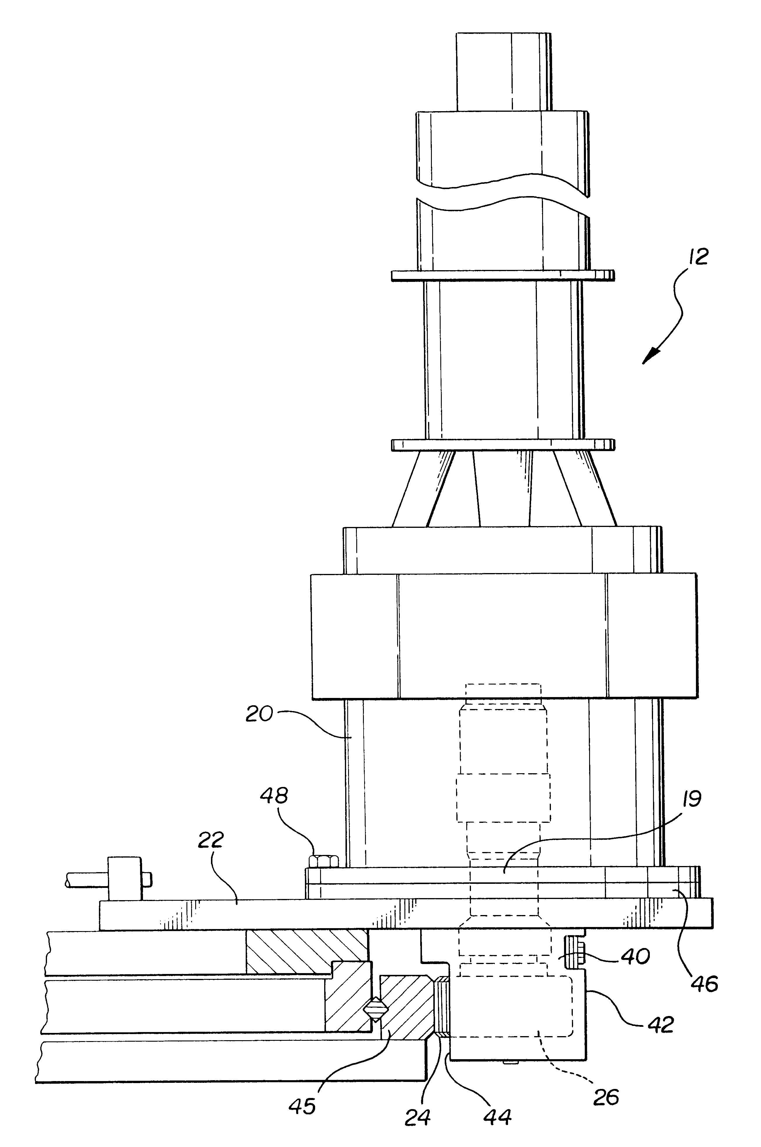
With reference now to FIGS. 2 and 3, the motor 18 drives a gear box 20 which is rigidly secured to a frame 22 of the framing system 10. An output or drive pinion 24 is selectably rotatably driven by a drive shaft 19 from the gear box 20 in order to index the turret 12 through the gear wheel 45. This pinion 24 includes an outer end 26 as well as an axial cylindrical recess 28 (FIG. 3) at its outer end 26....


PUM


Abstract

A pinion support is disclosed for use with a motor set on a gear box casing and an output drive pinion having an axial recess at the outer end of the pinion. The pinion support includes a housing which is rigidly secured against movement to the gear box casing and includes a portion which overlies the outer end of the pinion. A pin is rigidly secured to the portion of the housing and this pin extends coaxially into the axial recess at the outer end of the pinion. A bearing assembly is operatively positioned between an outer surface of the pin and an inner surface of the pinion recess. The pinion support is particularly well suited for use in an automotive framing system.

Description

I. Field of the InventionThe present invention relates to a pinion support for supporting a free end of a pinion when operating in restricted room condition.II. Description of the Prior ArtActuator motors with gear boxes are used in many industrial applications, such as an automotive framing system. In an automotive framing system, a motor set on a gear box is rigidly secured to a turret frame. The motor, upon actuation, rotatably drives a pinion which protrudes outwardly from one end of a gear box.In many applications, such as an automotive framing system, the precise rotational position of the pinion is required for accurate and satisfactory operation of the entire system. In many such applications, however, the pinion is subjected to high torque which may result in slight flexing of the pinion away from the load. Any such flexing not only results in unsatisfactory oscillation of the system, but can also result in inaccurate positioning of the load driven by the motor / gear box, an...

Claims


Application Information

Patent Timeline
Patent Type & Authority Patents(United States)
IPC IPC(8): B23Q5/22B23Q5/38
CPCB23Q5/385Y10T74/1488
Inventor BAULIER, DOMINIQUE R. M.SOLCZ, LEONARD
Owner VALIANT CO LTD
Learn More