
Integrated fuel injector orientation and retention device

a fuel injector and integrated technology, applied in the direction of fuel injection apparatus, couplings, charge feed systems, etc., can solve the problems of fuel injectors not without improvement, parts that are not in good alignment,

Active Publication Date: 2015-04-07
DENSO INTERNATIONAL AMERICA +1
View PDF9 Cites 3 Cited by
  • Summary
  • Abstract
  • Description
  • Claims
  • Application Information

AI Technical Summary

Benefits of technology

The patent text describes a design for a tab that helps to securely attach components together. The tab has a solid head portion with two outside walls that form a gap. This design prevents the head from flexing when the walls come into contact with each other. The tab also has an angle between the entry contact surface and the prong interior straight wall surface that is smaller than the angle between the exit contact surface and the prong's outside wall surface. This reduces friction and allows for smoother assembly.

Problems solved by technology

While current fuel injectors and corresponding fuel rails have been satisfactory for their given applications, such components are not without need for improvement.
During shipment of fuel injectors or during assembly of a fuel rail and an injector combination onto an engine, because only an O-ring is compressed against an interior of the injector cup, the integrity of the holding force of the compressed O-ring may be compromised, resulting in parting of the injector from the injector cup or misalignment of the parts prior to installation onto an engine.
Moreover, during operation, fuel injectors may become stuck or seized onto the engine cylinder head due to soot or carbon build-up at the tip of the injector.

Method used


Image

  • Integrated fuel injector orientation and retention device
  • Integrated fuel injector orientation and retention device
  • Integrated fuel injector orientation and retention device

Examples


Embodiment Construction

[0027]Example embodiments will now be described more fully with reference to the accompanying drawings. The following description is merely exemplary in nature and is not intended to limit the present disclosure, application, or uses. When an element or layer is referred to as being “on”, “engaged to”, “connected to” or “coupled to” another element or layer, it may be directly on, engaged, connected or coupled to the other element or layer, or intervening elements or layers may be present. In contrast, when an element is referred to as being “directly on,”“directly engaged to”, “directly connected to” or “directly coupled to” another element or layer, there may be no intervening elements or layers present. Other words used to describe the relationship between elements should be interpreted in a like fashion (e.g., “between” versus “directly between,”“adjacent” versus “directly adjacent,” etc.). As used herein, the term “and / or” includes any and all combinations of one or more of the...


PUM


Abstract

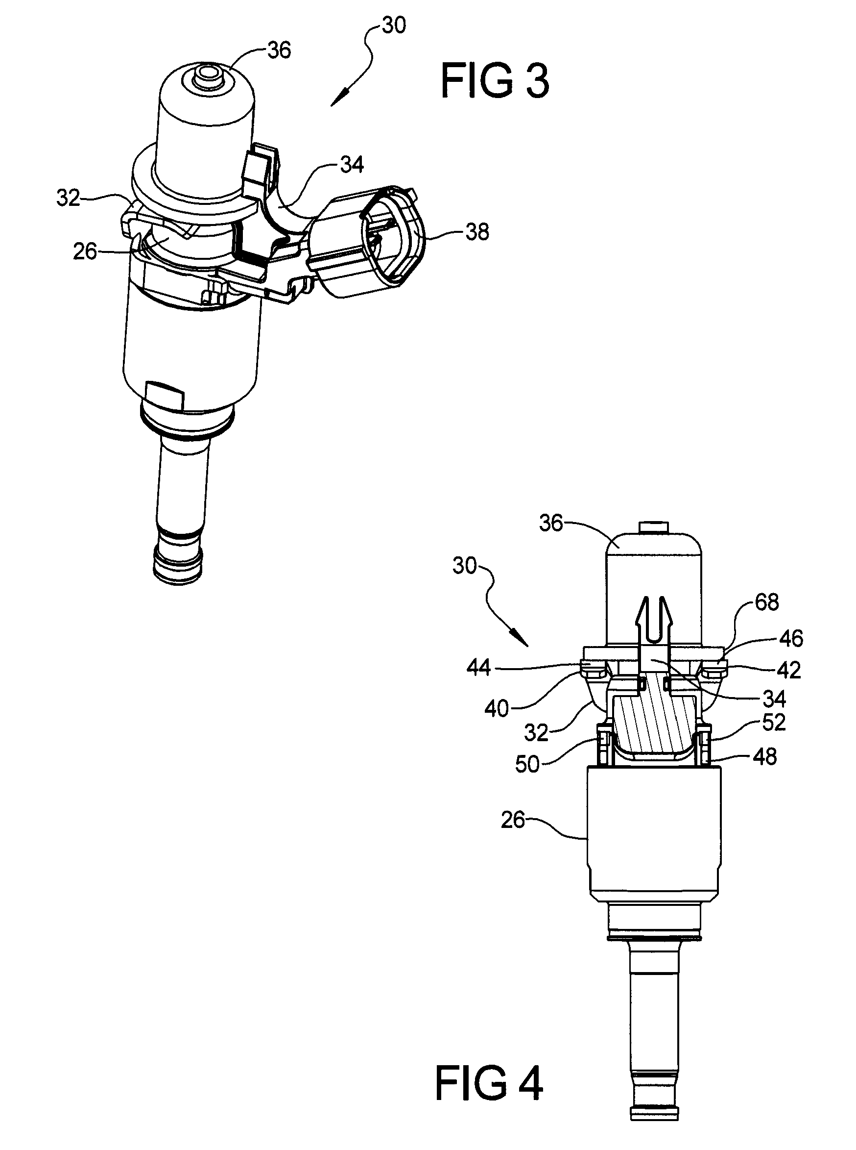
Attaching a fuel injector to a common rail may utilize a fuel injector and an integral tab that has a solid head portion from which a first flexible prong and a second flexible prong protrude and define a gap therebetween. A fuel injector cup may define a notch through which the first prong and the second prong reside to secure the fuel injector to the fuel injector cup, which is attached to the rail. A first prong interior straight wall surface and a second prong interior straight wall surface may face the gap and be parallel. The prongs may define entry contact surfaces and exit contact surfaces that meet at prescribed angles to aid in insertion and hinder retraction of the injector tab from the injector cup. The tab defines a solid head portion below the gap that resides in the notch.

Description

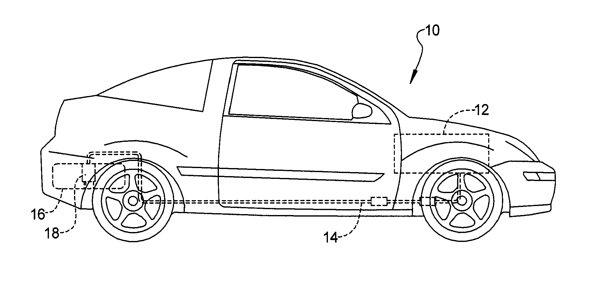
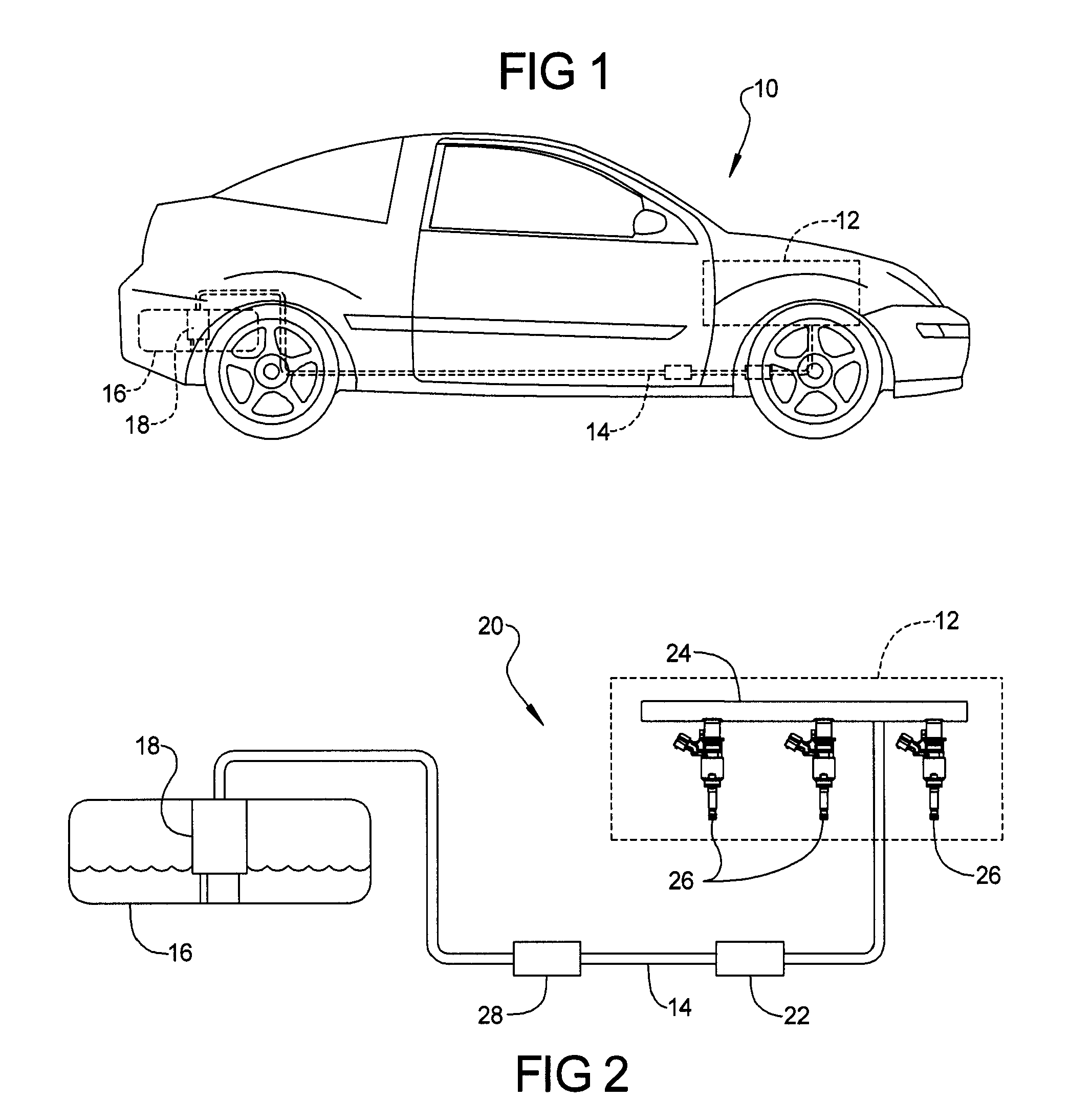
FIELD[0001]The present disclosure relates to a structure to aid in orientation and retention of a fuel injector to a fuel rail.BACKGROUND[0002]This section provides background information related to the present disclosure which is not necessarily prior art. Internal combustion engines such as direct injection engines may employ fuel injectors that provide a fluid conduit between a pressurized fuel rail and a combustion cylinder of an internal combustion engine. While current fuel injectors and corresponding fuel rails have been satisfactory for their given applications, such components are not without need for improvement.[0003]Engine assemblers desire a tight, secure and aligned assembly of the fuel injector to the fuel rail to prevent disassembly during part shipment and during installation of the fuel rail and fuel injectors onto the engine. Additionally, prevention of a fuel injector from becoming misaligned with the fuel rail during assembly onto an engine or prior to assembly ...

Claims


Application Information

Patent Timeline
Patent Type & Authority Patents(United States)
IPC IPC(8): F02M61/14
CPCF02M61/14
Inventor ROSEBORSKY, STEVEN R.RAMAMURTHY, DHYANA
Owner DENSO INTERNATIONAL AMERICA
Learn More