Dual flight rotors for continuous mixer assembly

a technology of mixer assembly and rotor, which is applied in the direction of mixing/kneading with horizontally mounted tools, rotary stirring mixers, clay mixing apparatuses, etc. it can solve the problems of elongated rotor pairs, requiring major rotor construction, and elongating rotor pairs to deflect, so as to increase the root diameter of the mixing rotor and avoid flexing. , the effect of increasing the structural strength

Inactive Publication Date: 2006-01-12
TECHN PROCEES & ENG
View PDF0 Cites 6 Cited by
  • Summary
  • Abstract
  • Description
  • Claims
  • Application Information

AI Technical Summary

Benefits of technology

[0008] It is another object of the present invention to increase the root diameter of the mixing rotor significantly, which serves to increase its structural strength and obviates its flexing from materials binding with it during processing.

Problems solved by technology

Materials mixing rotors with standard threads, configured as depicted in prior art FIG. 1 and 2, were seen to be breaking down, and would not run for more than a few weeks, causing down time and requiring major rotor construction, if salvageable.
Such prior art rotors were wrapping molten materials about their periphery, creating pinch points, that caused the elongate rotor pairs to deflect.
Such repetitive deflection eventually caused rotor cracking, and operational breakdown.
Thus, the standard threaded rotor was structurally weakened and gave only limited and costly operational longevity when using standard threads on flights throughout the mixing length.

Method used


Image

  • Dual flight rotors for continuous mixer assembly
  • Dual flight rotors for continuous mixer assembly
  • Dual flight rotors for continuous mixer assembly

Examples


Embodiment Construction

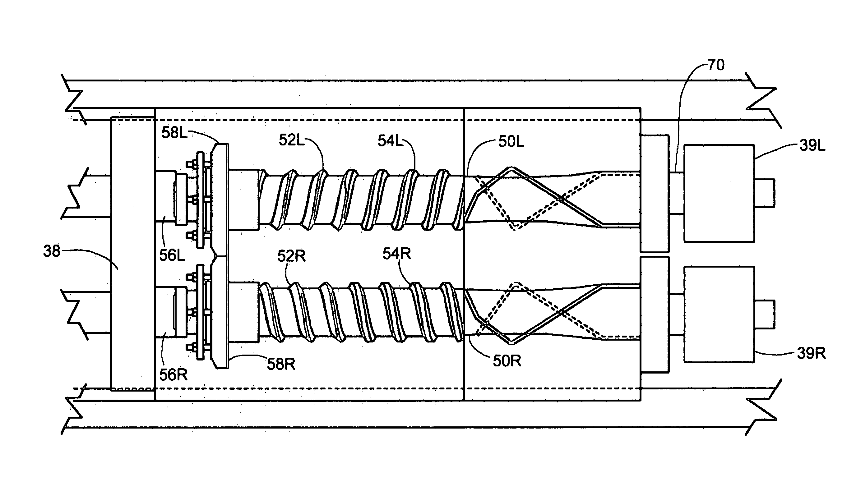
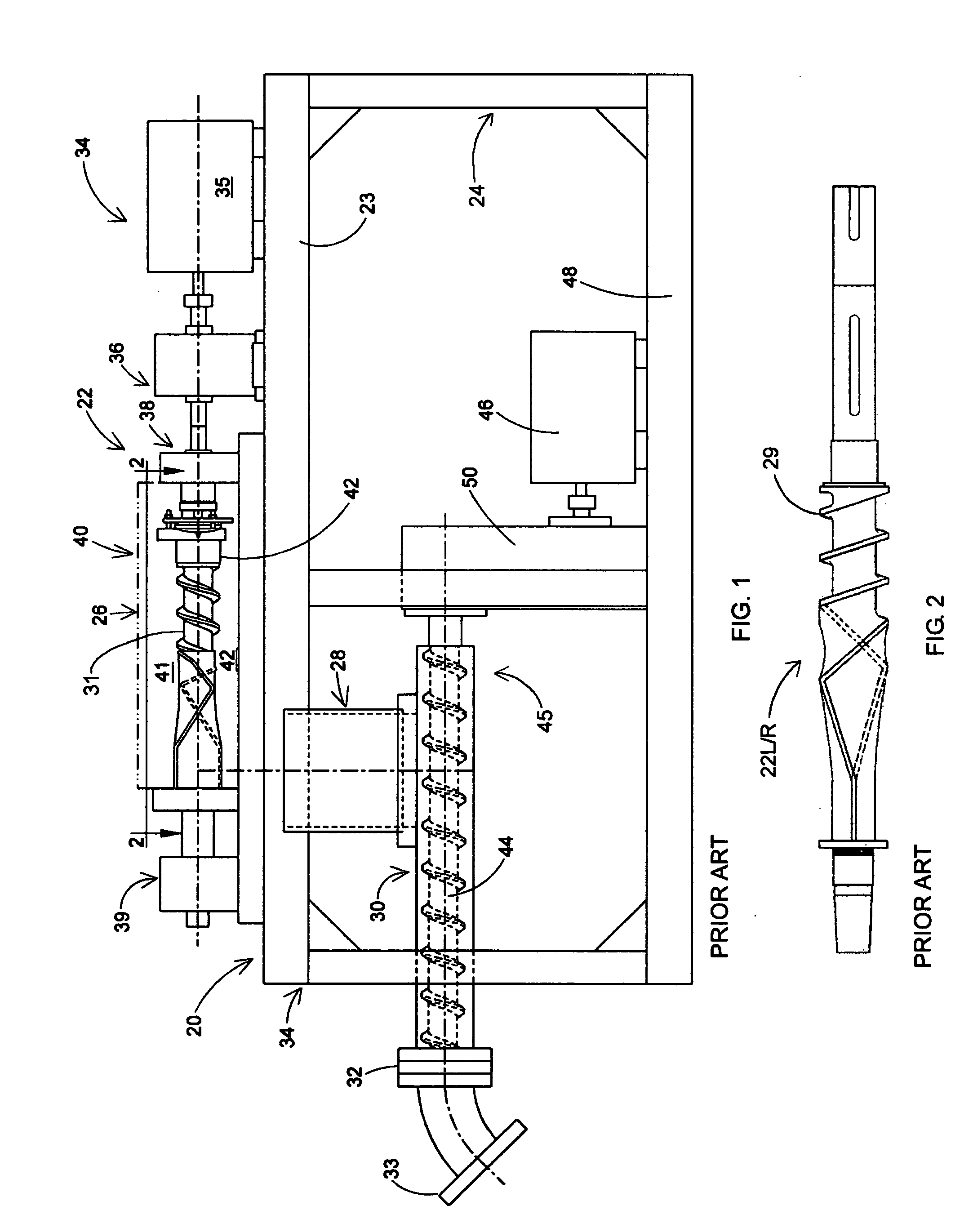
[0021] With reference to FIG. 1, there is shown a prior art, compact processor 20 for plastic materials and comprising a unitized mixing and extrusion system that allows a user to customize mixing and extrusion of the plastic materials being processed. This unitized processor system comprises a two-rotor, continuous mixer 22 mounted on an upper level 23 of a framework 24. Plastic materials, fillers, additives, colorants, and the like, namely various ingredients desired to be mixed with plastic materials, as desired by the user, are introduced into a feed entrance (sometimes called a “feed throat”) of the continuous mixer 22, as indicated by an arrow 26. The resulting molten plastic materials flow by gravity downward from the continuous mixer 22, like a molten “rope”, descending within a vertical chute 28, into a hot-feed extruder 30. Standard screw type threads 29 (FIG. 2) are used on rotor 31. The molten output from the extruder 30 (FIG. 1) issues through an extruder head 32, which...


PUM

PropertyMeasurementUnit
outer diameteraaaaaaaaaa
lengthaaaaaaaaaa
lengthaaaaaaaaaa

Abstract

In the field of continuous mixer apparatus for commingling particulate thermoplastic materials, employing at least one main rotor with a helical profile body configuration, an improved profile for the peripheral threads is provided. It presents a first upstream feed flight having a plurality of Lowenherz profile outer threads and second downstream feed flight having a plurality of screw-type outer threads, both being adjacent and integral with the periphery of the main rotor.

Description

CROSS-REFERENCE TO OTHER APPLICATIONS [0001] None. FIELD OF THE INVENTION [0002] This is an examinable patent application under Code Section 111(a) submitted for a formal filing receipt and examination. The present invention lies in the field of plastic materials mixing in continuous mixer assemblies. BACKGROUND OF THE INVENTION [0003] Materials mixing rotors with standard threads, configured as depicted in prior art FIG. 1 and 2, were seen to be breaking down, and would not run for more than a few weeks, causing down time and requiring major rotor construction, if salvageable. Such prior art rotors were wrapping molten materials about their periphery, creating pinch points, that caused the elongate rotor pairs to deflect. Such repetitive deflection eventually caused rotor cracking, and operational breakdown. Thus, the standard threaded rotor was structurally weakened and gave only limited and costly operational longevity when using standard threads on flights throughout the mixing ...

Claims


Application Information

Patent Timeline
Patent Type & Authority Applications(United States)
IPC IPC(8): B29B7/00
CPCB29B7/465B29B7/7461B29C47/38B29C47/0871B29C47/0009B29C48/03B29C48/268B29C48/395
Inventor ZIEGENFUS, KELLY A.ALTENBURG, H. SLAYTONWOODRING, DONALD E.SCHAFER, HAROLD L. JR.HOWER, JAMES
Owner TECHN PROCEES & ENG
Why Eureka
Try Eureka