Rotary snow plow

a rotary and snow plow technology, applied in snow cleaning, way cleaning, construction, etc., can solve the problems of drifting from the correct position, demanding snowboarders are not satisfied with riding on ordinary ski courses,

Inactive Publication Date: 2002-04-09
ZAUGG EGGIWIL
View PDF11 Cites 12 Cited by
  • Summary
  • Abstract
  • Description
  • Claims
  • Application Information

AI Technical Summary

Problems solved by technology

Demanding snowboarders however are not satisfied with riding on ordinary ski courses, but look for a challenge in specially prepared, channel-like snow vales which are called half pip

Method used


Image

  • Rotary snow plow
  • Rotary snow plow
  • Rotary snow plow

Examples


Embodiment Construction

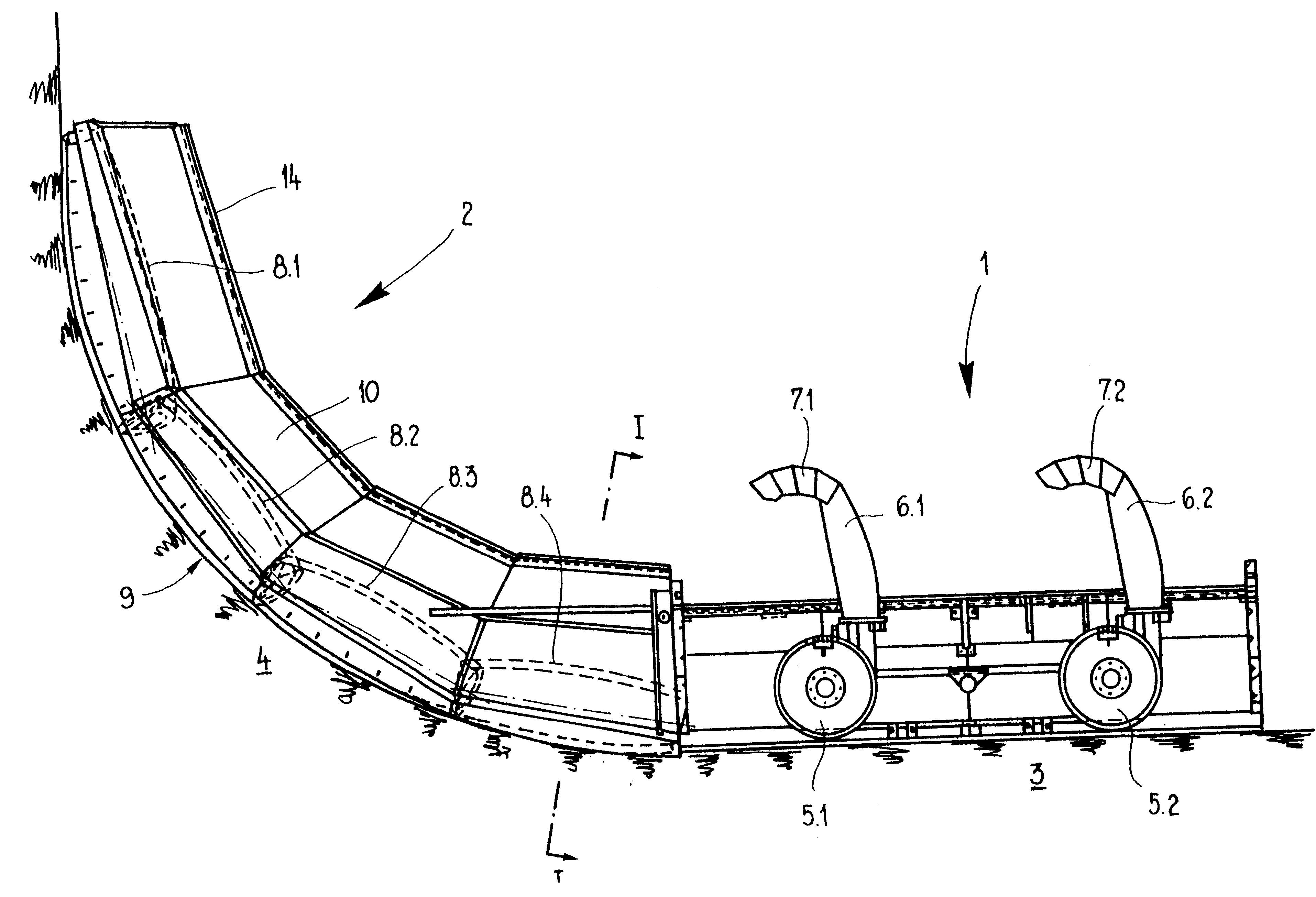
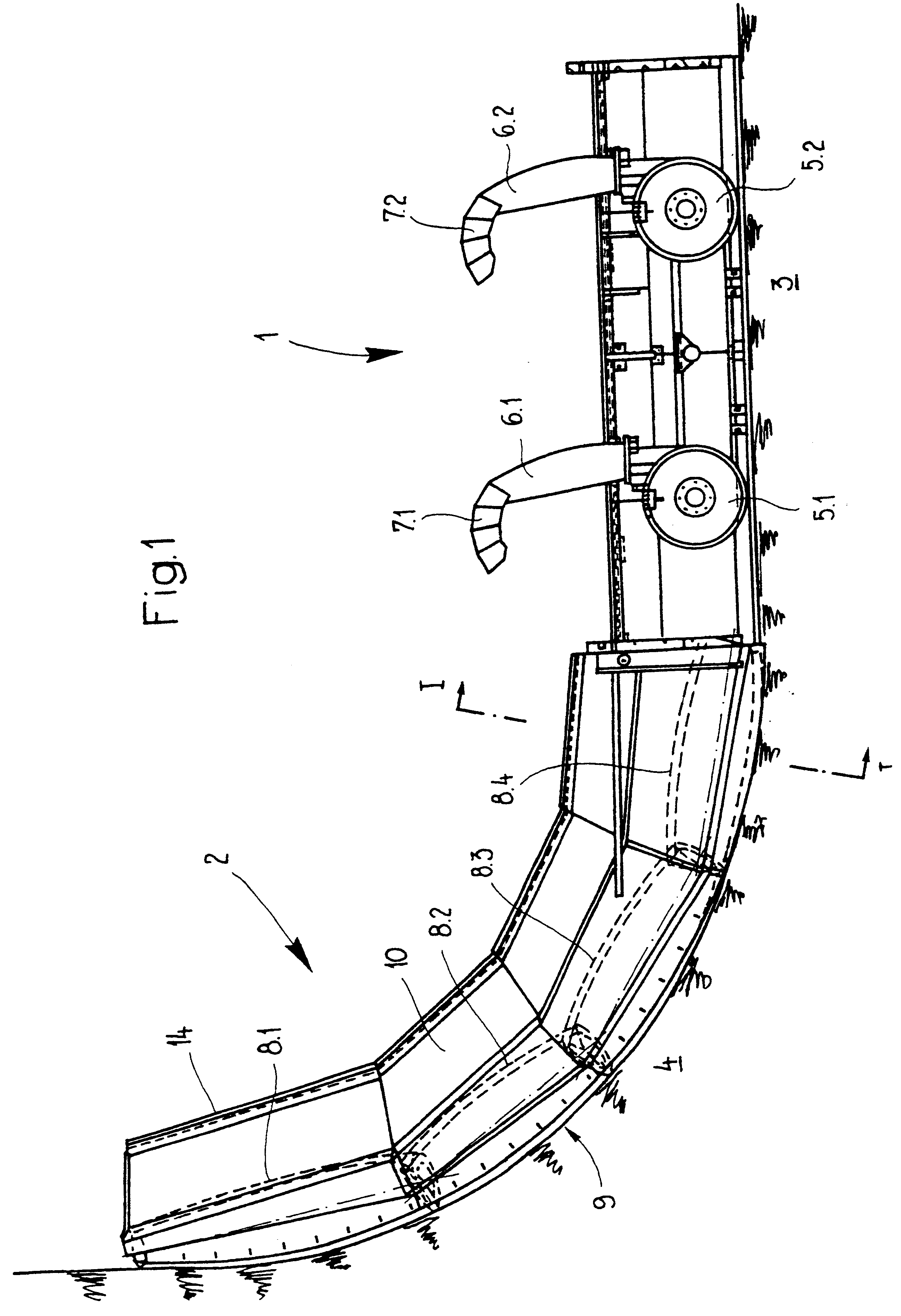
The object of the invention is to devise a rotary snow blower plow of the initially mentioned type which is characterized by increased efficiency.

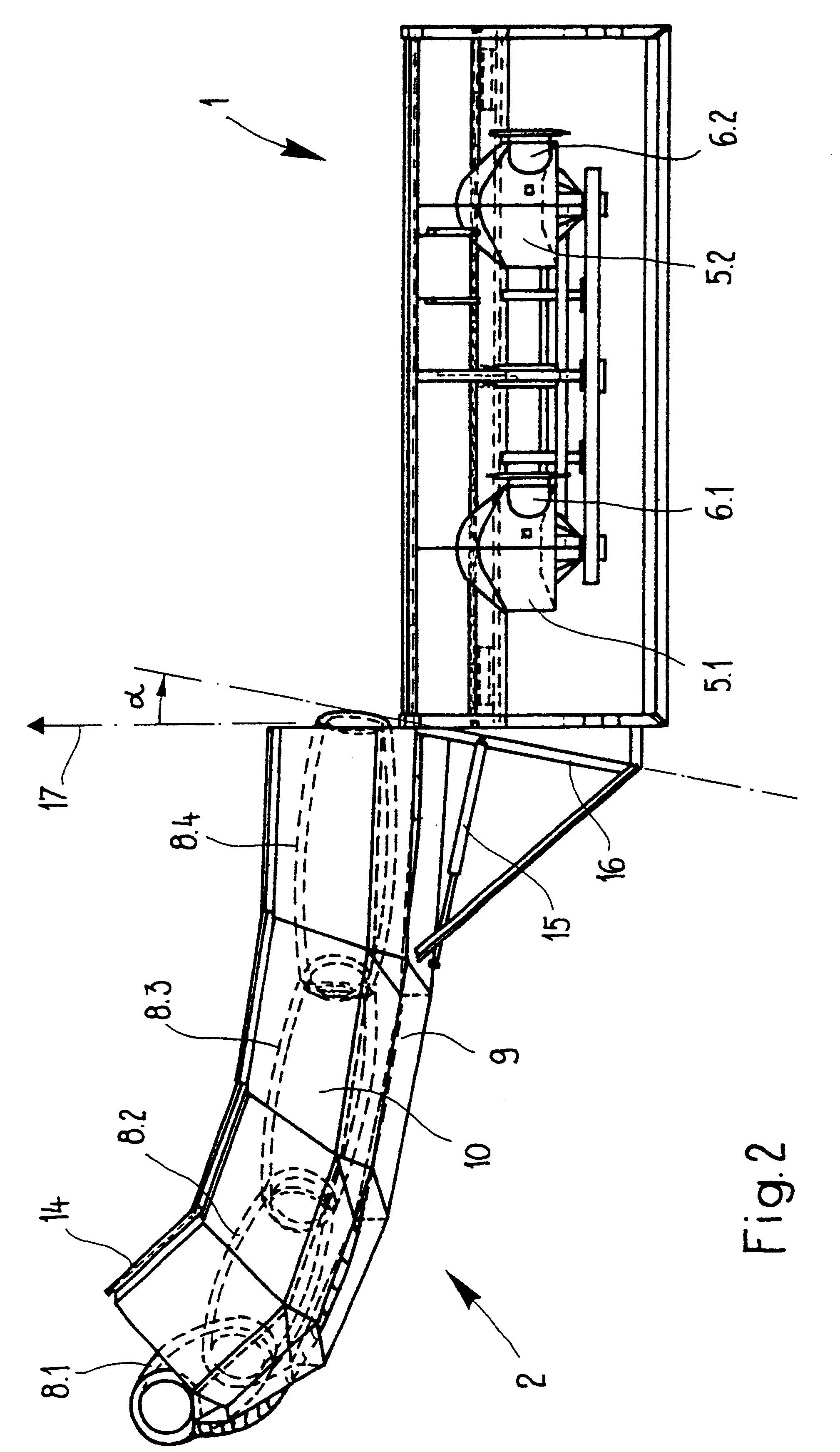
According to the invention, the fan blower is located on one line (i.e. on the same geometrical axis) with the plow worm.

In contrast to the convention rotary snow blower plows, in the invention the flow of snow need not be deflected by 90.degree. to supply the fan blower. This benefits the efficiency and the power consumed. The invention is especially suitable for side wall clearing and preparation of half pipe courses.

Especially good efficiency can be achieved by the fact that the fan blower and the plow worm are attached on a common shaft. The fan blower and plow worm are therefore rigidly coupled to one another to rotate. The drive can be structurally made relatively simple as a result.

Preferably the device is equipped with a hydraulic drive. This is supplied by the utility vehicle. Instead of a hydraulic drive a mechanical one can also...


PUM


Abstract

The rotary snow blower plow with a plow worm (18) which delivers the snow and a fan blower (19) which throws the delivered snow. The fan blower (19) is located on a line with the plow worm (18). The fan blower (19) and the plow worm (18) can be mounted on a common shaft (23) so that they rotate with the same angular speed. The rotary snow blower plow is characterized by high efficiency since the flow of snow need not be deflected by 90 degrees. It is especially suited for clearing of side walls and preparation of half pipe courses.

Description

The invention relates to a rotary snow blower plow with a plow worm which delivers the snow and a fan blower which throws the delivered snow. Furthermore the invention relates to a means with one such rotary snow blower plow.1. Prior ArtRotary snow blower plows are used to clear larger amounts of snow. On the one hand, they have a plow worm and on the other a fan blower. The plow worm breaks up the snow and delivers it to the fan blower, from which it is specifically thrown away via a chimney.Rotary snow blower plows are used not only in the municipal domain (roads, parking lots, etc.), but also to prepare ski and snowboard courses. In any case the user is interested in the rotary snow blower plow having efficiency as high as possible. If there is already a utility vehicle, with its (often limited) power a working speed as high as possible is to be reached. If a new utility vehicle is procured, the lower power consumption of the rotary snow blower plow has the advantage that savings...

Claims


Application Information

Patent Timeline
IPC IPC(8): E01H5/04E01H4/00E01H4/02E01H5/09
CPCE01H4/02E01H5/098E01H2004/026
Inventor ZAUGG, WERNERMAURER, KLAUS
Owner ZAUGG EGGIWIL
Why Eureka
Try Eureka