Drive assistance apparatus for a vehicle having a main transmission that is mechanical

Inactive Publication Date: 2002-04-09
POCLAIN HYDRAULICS IND
View PDF9 Cites 45 Cited by
  • Summary
  • Abstract
  • Description
  • Claims
  • Application Information

AI Technical Summary

Benefits of technology

The present invention seeks to propose an apparatus to which changeover from the free-wheel configuration to the working configuration takes place under better conditions, thus making it possible to pe

Problems solved by technology

When the pistons are caused to move out from their cylinders so as to place their free ends (possibly fitted with wheels) in contact with the cam, this contact takes place suddenly, giving rise to shocks between the pistons and the cam, which ru

Method used


Image

  • Drive assistance apparatus for a vehicle having a main transmission that is mechanical
  • Drive assistance apparatus for a vehicle having a main transmission that is mechanical
  • Drive assistance apparatus for a vehicle having a main transmission that is mechanical

Examples


Embodiment Construction

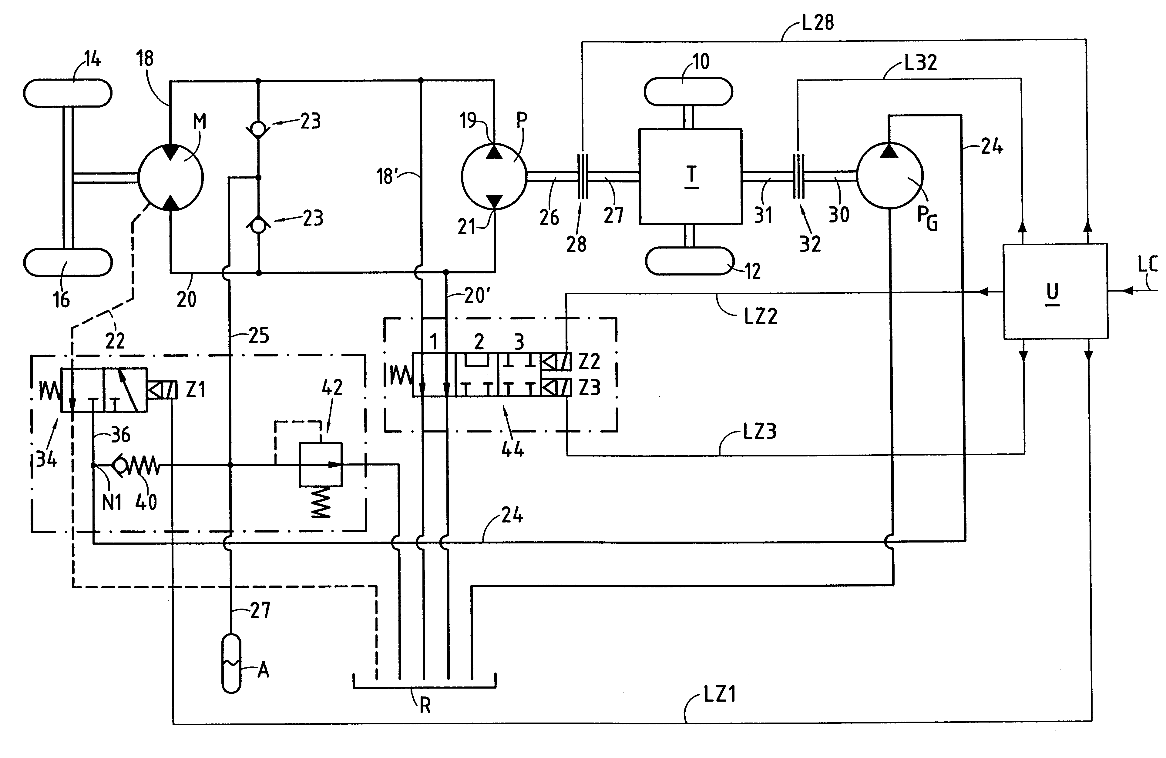
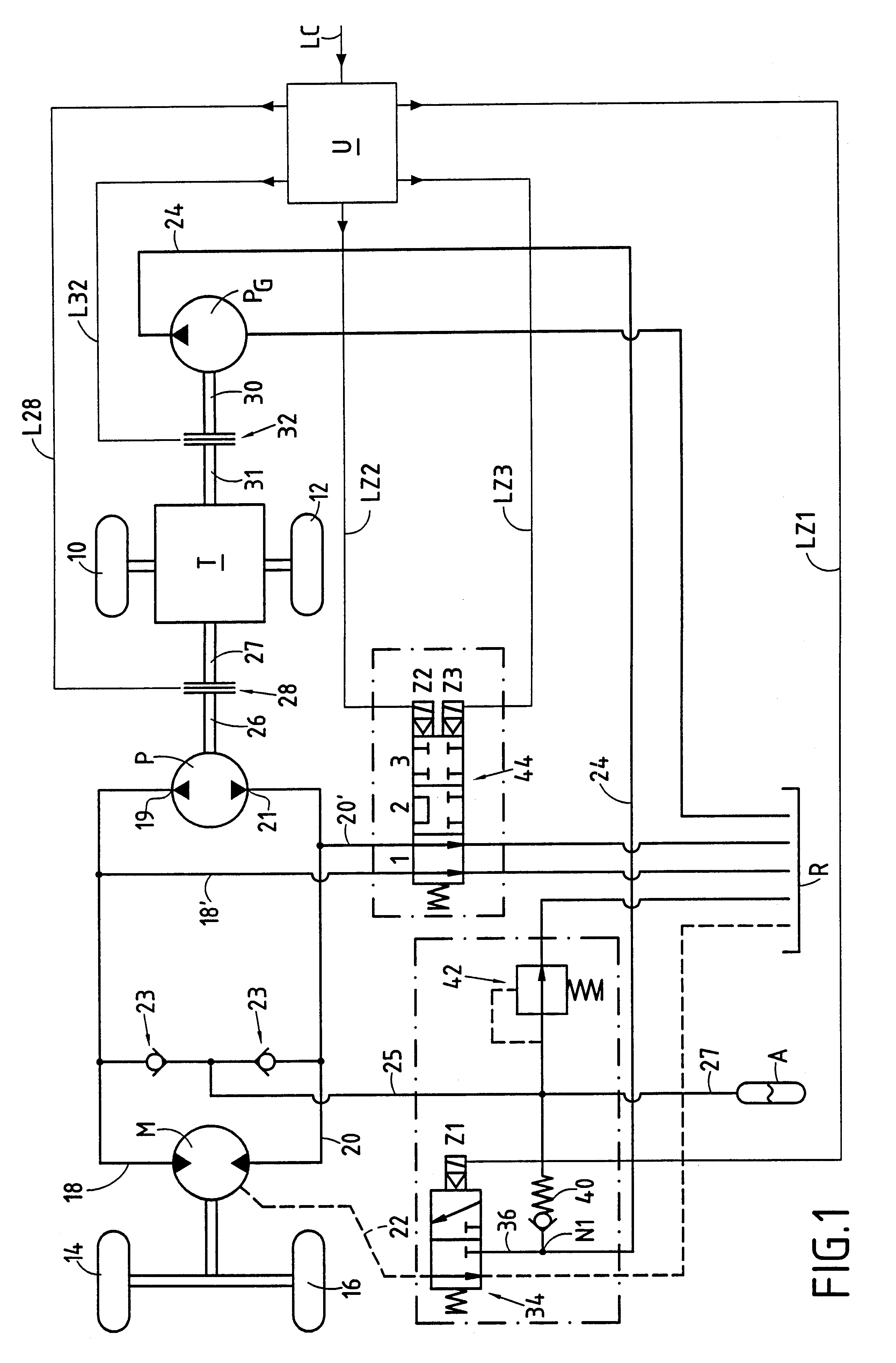
The circuit shown in FIG. 1 comprises a transmission T having coupled thereto the wheels 10 and 12 of a first axle of a vehicle. The transmission T is the main mechanical transmission of the vehicle and it is used for propelling the vehicle under normal conditions, for example on the road.

FIG. 1 also shows a hydraulic motor M having coupled thereto the wheels 14 and 16 of a second axle of the vehicle. The motor M is an assistance hydraulic motor and it is used to assist the transmission T, i.e. to exert an additional drive force on the wheels 14 and 16 of the second axle while the wheels 10 and 12 continue to be driven by the transmission T.

In conventional manner, the motor M is a hydraulic motor having radial pistons, comprising a stator and a rotor. It can be a motor having a rotary case, in which case the rotor comprises the case and the cam of the motor, while the stator comprises its cylinder block, or else it can be a motor having a rotary shaft, in which case the cylinder blo...


PUM


Abstract

Apparatus for providing drive assistance in a vehicle having a main transmission that is mechanical. The apparatus comprises a hydraulic motor of the type having radial pistons that is powered by a main pump. The pistons can be retracted into their cylinders in a free-wheel configuration of the motor or they can co-operate with the reaction member of the motor when they are in a working configuration. The apparatus comprises means for implementing successive stages of a sequence for causing the motor to pass from its free-wheel configuration to its working configuration. The sequence comprises an initialization stage in which the case of the motor is filled with fluid at a "service" pressure by means of an auxiliary duct and a service duct, and in which the main feed and exhaust ducts of the motor are placed at a filling pressure that is lower than the service pressure. The sequence then comprises a clutch engagement stage during which the inside space of the case is connected to a fluid return tank and during which the main ducts are isolated from each other.

Description

The present invention relates to a drive assistance apparatus for a vehicle having a mechanical main transmission for driving displacement members of the vehicle, the apparatus comprising a main source of fluid under pressure suitable for being driven by first drive means to deliver fluid under pressure, and at least one hydraulic motor suitable for being fed with fluid under pressure by the main source of fluid to drive at least one displacement member of the vehicle, said motor having a stator and a rotor suitable for rotating relative to the stator about an axis of rotation, the motor comprising a cylinder block which belongs to a first one of the two elements constituted by the stator and the rotor, which is disposed inside a case, and which presents a plurality of cylinder-and-piston assemblies disposed radially relative to the axis of rotation, together with a reaction member for the pistons which belongs to the second one of said two elements, the motor also having a main flu...

Claims


Application Information

Patent Timeline
IPC IPC(8): B60K17/34B60K23/08B60K17/356B60K23/06B60K23/00B60K17/10
CPCB60K23/08B60K17/356B60K17/02B60K17/10B60K23/06
Inventor MALETSCHEK, KARL-GUNTHERROUILLARD, JEAN-MARIE
Owner POCLAIN HYDRAULICS IND
Why Eureka
Try Eureka