Etching method and a method of manufacturing a magnetic head

a manufacturing method and magnetic head technology, applied in the field of etching method and manufacturing method of magnetic head, can solve the problems of mr element wearout, inability to detect reproducible signals for a conventional inductive type magnetic head using electromagnetic induction, and so on

Inactive Publication Date: 2002-04-09
SONY CORP
View PDF3 Cites 4 Cited by
  • Summary
  • Abstract
  • Description
  • Claims
  • Application Information

AI Technical Summary

Problems solved by technology

However, if the magnetic recording medium is improved to have a high recording density in a magnetic recording system, the magnetized information from the magnetic recording medium is so weakened that reproduced signals are difficult to detect for a conventional inductive type magnetic head using electromagnetic induction.
However, in case where the MR head is set in a helical scan tape system in which the magnetic head is mounted on a rotation drum and recording / reproducing is carried out while rotating the magnetic head, the MR element must be slid on a magnetic tape at a high speed, leading to a problem that the MR element is worn out.
Once the MR element is worn out, serious problems are caused, e.g., the output and the bias amount changes, the operation stability is lowered, the resistance value changes, or so.
In the conventional methods as described above, since yoke cores are formed one after another, the manufacturing steps are complicated.
Also, in the second forming method, a difference in thickness appears between the yoke cores and causes a drawback that the off-track characteristic is deteriorated.

Method used


Image

  • Etching method and a method of manufacturing a magnetic head
  • Etching method and a method of manufacturing a magnetic head
  • Etching method and a method of manufacturing a magnetic head

Examples


first embodiment

In the following, the present invention will be specifically explained with reference to the drawings.

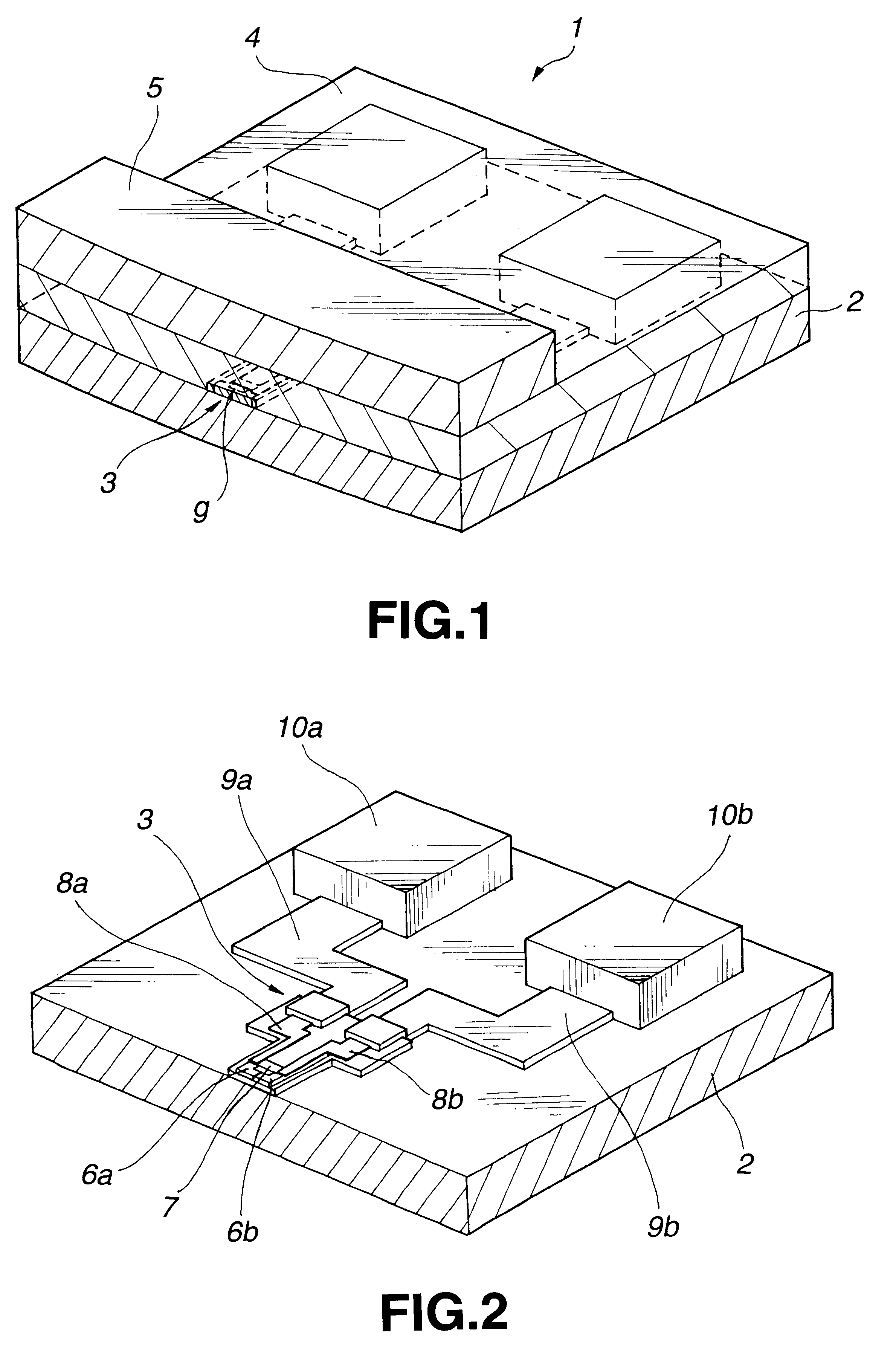
An example of a structure manufactured by the method adopting the present invention will be shown in FIGS. 1 and 2. The MR head 1 comprises a first substrate 2, an MR head element 3 formed on the first substrate 2, a protect film 4 formed on the MR head element 3, and a second substrate 5 bonded on the protect film 4. FIG. 1 is a perspective view showing an example of the MR head 1, and FIG. 2 is a perspective view showing the structure of the MR head element 3 where the protect film 4 and the second substrate 5 are removed therefrom.

The first substrate 2 and the second substrate 5 serve as guard materials for the MR head element 3, and a hard material having a high resistivity such as calcium titanate or the like is used. Meanwhile, Al2O3 or the like is used for the protect film 4.

Further, as shown in FIG. 2, the MR head element 3 comprises a pair of yoke cores 6a and 6b arranged a...

second embodiment

By the steps as described above, the MR head 1 is completed.

When the MR head 1 according to the first or second embodiment is used in a helical scan tape system, for example, it is used attached to a rotation drum 20.

The MR head 1 as described above is capable of solving effectively the problem caused due to friction of the magnetic resistance effect element and is therefore very advantageous, when the head is used in a system such as a helical scanning system in which the head slides on a tape-like magnetic recording medium at a high speed to record / reproduce information. However, the MR head 1 is also applicable to a system in which the head slides on a disk-like magnetic recording medium.

Although the above embodiments have been explained with reference to a case where a mask made of Cr is used when etching the SiO2 film forming the magnetic gap. However, the present invention is not limited to this case but any masks made of various materials can be used regardless of whether th...


PUM

PropertyMeasurementUnit
thicknessaaaaaaaaaa
thicknessaaaaaaaaaa
widthaaaaaaaaaa

Abstract

A magnetic gap is formed to be vertical to the film forming surface of a substrate with high accuracy by a simple method. The method comprises a non-magnetic film forming step of forming a non-magnetic film made of the non-magnetic material on the substrate, a high selectivity film forming step of forming a high selectivity film made of a material which has a higher selectivity ratio with respect to reactive ion etching than the non-magnetic material, on the non-magnetic film formed, a patterning step of patterning the high-selectivity film into a predetermined shape, and an etching step of etching the non-magnetic film by reactive ion etching, using the high selectivity film as a mask.

Description

RELATED APPLICATION DATAThe present application claims priority to Japanese Application No. P10-353341 filed Dec. 11, 1998 and Japanese Application No. P11-070792 filed Mar. 16, 1999, which applications are incorporated herein by reference to the extent permitted by law.1. Technical FieldThe present invention relates to an etching method and a method of manufacturing a magnetic head, and more specifically, to a method of manufacturing a magnetic head in which a magnetic gap is formed between non-magnetic materials provided on opposed surfaces of a pair of yoke cores which are formed to be opposed to each other on a substrate.2. Background ArtIn recent years, video tape recorders, audio tape recorders, computer data storage systems, and the like are known as magnetic recording / reproducing apparatuses which use a magnetic tape as a recording medium. As for the magnetic recording medium, there is a demand for increasing the recording density to enhance its capacity and to attain a high...

Claims


Application Information

Patent Timeline
Patent Type & Authority Patents(United States)
IPC IPC(8): C23F4/00G11B5/31G11B5/39G11B5/53
CPCC23F4/00G11B5/3116G11B5/313G11B5/3163G11B5/3925G11B5/3183Y10T29/49032G11B5/53Y10T29/49052
Inventor KATAKURA, TORUMIYAUCHI, TEIICHITAKANASHI, YUKO
Owner SONY CORP
Why Eureka
Try Eureka