Optical flow sensor

a flow sensor and optical technology, applied in the field of optical flow sensors, can solve the problems of inaccurate flow rate measurement, insufficient estimate of flow rate achieved with such instruments, and inability to meet industrial and environmental applications

Inactive Publication Date: 2002-04-09
OPTICAL SCI
View PDF4 Cites 16 Cited by
  • Summary
  • Abstract
  • Description
  • Claims
  • Application Information

AI Technical Summary

Problems solved by technology

Accurate flow rate measurement represents one of the biggest problems in industrial and environmental monitoring for contaminants in gaseous discharges.
While the determination of the concentration of pollutants, contaminants, noxious gases, and toxic gases in a gas flow has reached a satisfactory level of reliability, monitoring of the rate, and hence the volume of gas flow, has heretofore been rather inaccurate.
The estimates for flow rate achieved with such instruments are often inadequate for industrial and environmental applications.
One problem is that the intrusion of a sensor head into the flow medium, alters the resulting flow measurements.
Furthermore, the flow medium being monitored is often very dirty and corrosive.
Direct con

Method used


Image

  • Optical flow sensor
  • Optical flow sensor
  • Optical flow sensor

Examples


Embodiment Construction

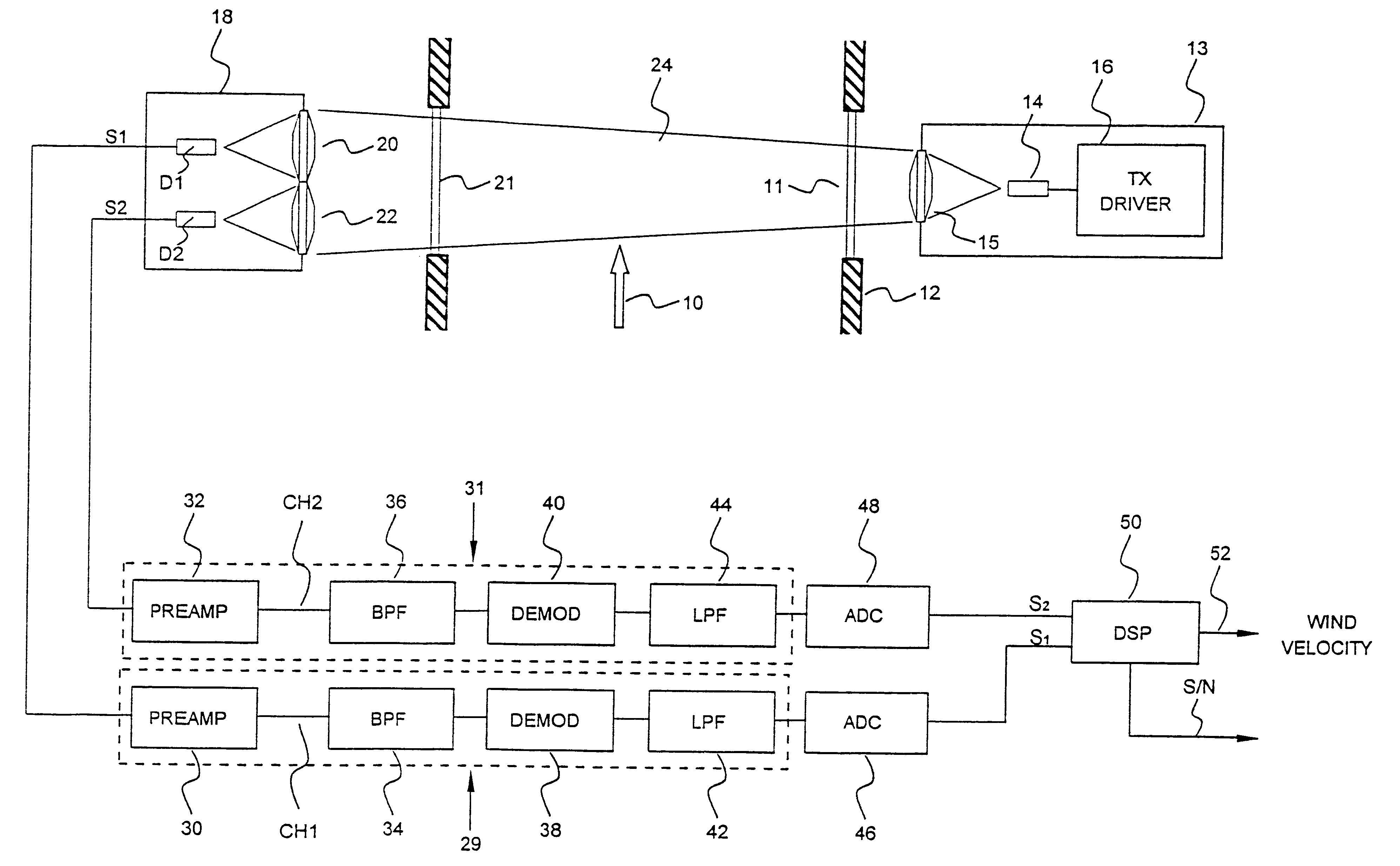
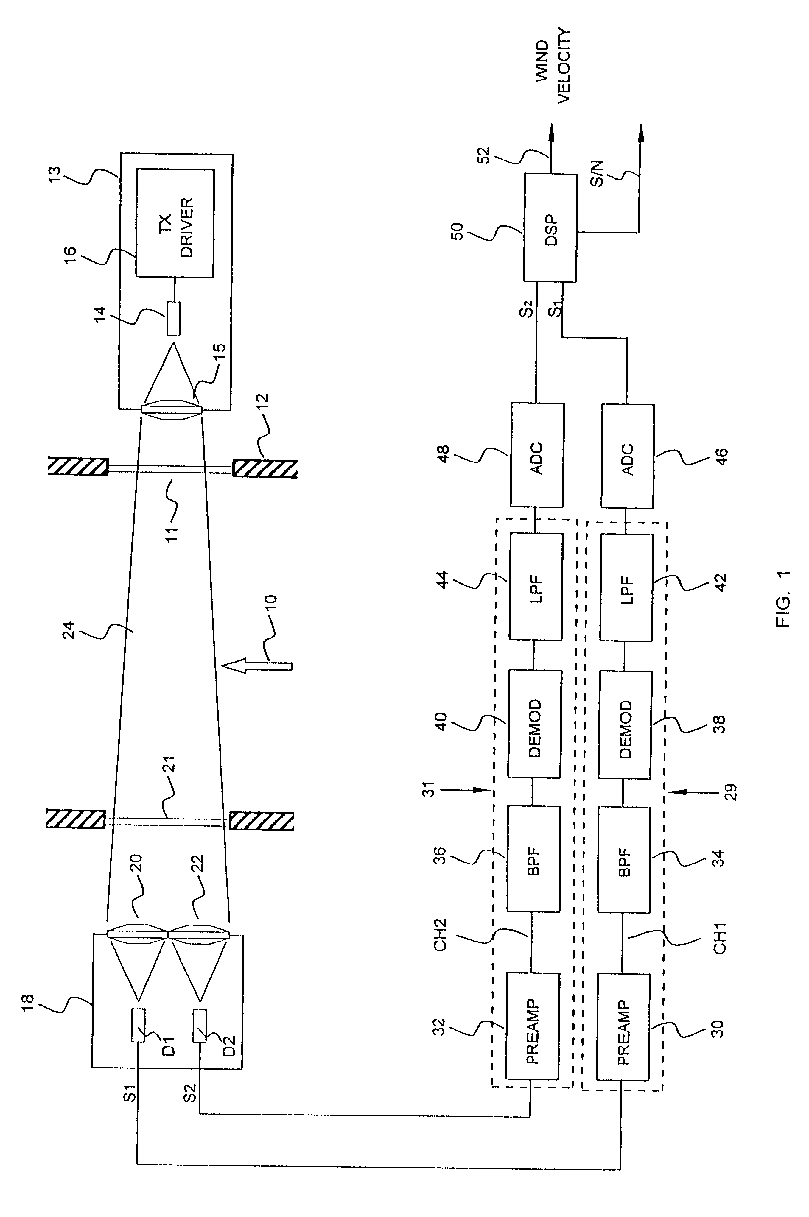
FIG. 1 illustrates diagrammatically an optical flow sensor for measuring gas flow velocity in a predetermined linear direction, indicated by the arrow 10 within an elongated, vertically oriented chimney 12 which may, for example, have a diameter of about 10 feet and a length of 30 feet or more. Only a short section of the chimney 12 is shown in FIG. 1.

The optical flow sensor includes a transmitter 13 having a laser diode or an LED 14 located in front of the chimney window 11 and driven by a transmitter driver 16. The transmitter 13 includes an optically transparent collimating lens 15. A receiver 18 is located on the wall of the chimney 12 diametrically opposite the transmitter 13, and includes a pair of receiving lenses 20 and 22 which are in line-of-sight communication with an optical beam 24 produced by the transmitter 13. The beam 24 is directed diametrically across the center of the chimney 12 to intersect the path of gas flow 10. The beam 24 falls upon both of the lenses 20 an...


PUM


Abstract

An optical flow sensor determines the velocity of a moving flow of air or other gas utilizing a plurality of photodetectors spaced apart in a direction parallel to the direction of gas flow. An optical beam is transmitted across the flowing gas and falls upon the photodetectors. Scintillations that occur in the flowing gas due to eddies and particulates in the gas are detected in all of the photodetectors, but at slightly different times due to the longitudinal separation of the photodetectors in the direction of gas flow. The output signals of the photodetectors are conditioned and amplified and transformed to digital form. Temporal cross correlation analysis is then performed on the digitized signals in a digital signal processor. A time differential between signals from the different photodetectors is then calculated electronically. The velocity of gas flow is then determined by dividing the spatial distance of separation between adjacent photodetectors by the time difference at which the same scintillation event is detected by each photodetectors.

Description

1. Field of the InventionThe present invention relates to an optical flow sensor which cross correlates digitized signals from a plurality of photodetectors that are separated in a direction parallel to a predetermined direction of gas flow and to a method of determining gas flow velocity in a predetermined direction.2. Description of the Prior ArtAccurate flow rate measurement represents one of the biggest problems in industrial and environmental monitoring for contaminants in gaseous discharges. The problem of airborne pollution has become so acute that virtually all industries of any size are now monitored for compliance with applicable regulations or laws limiting gaseous discharges. While the determination of the concentration of pollutants, contaminants, noxious gases, and toxic gases in a gas flow has reached a satisfactory level of reliability, monitoring of the rate, and hence the volume of gas flow, has heretofore been rather inaccurate. As a consequence. The determination...

Claims


Application Information

Patent Timeline
IPC IPC(8): G01F1/704G01F1/708G01F1/712G01P5/18G01P5/22G01P5/26G01P5/00G01F1/7086
CPCG01F1/7086G01P5/26G01P5/22G01F1/712
Inventor WANG, TING-I
Owner OPTICAL SCI
Why Eureka
Try Eureka