Disk drive with method of constructing a continuous position signal and constrained method of linearizing such position signal while maintaining continuity

a technology of magnetic disk drive and position signal, applied in the field of magnetic disk drive, can solve the problems of discontinuities of the indicator position signal of ordinary construction, mr head to exhibit a significant shift in the nominal value of the gain, and mr head to have an inherently non-linear microtrack profil

Inactive Publication Date: 2002-04-09
WESTERN DIGITAL TECH INC
View PDF7 Cites 153 Cited by
  • Summary
  • Abstract
  • Description
  • Claims
  • Application Information

AI Technical Summary

Benefits of technology

FIG. 13 shows how the indicated position signal of FIG. 12 may be linearized without destroying the continuity from fractional PES segment to fractional PES segment;

Problems solved by technology

An indicated position signal of ordinary construction, however, may have discontinuities owing to variations in the placement of the bursts during the servo writing process, non-linearity of the read head signals relative to true displacement from a burst pair centerline, or both.
Discontinuities are especially prevalent with the current use of magnetoresistive (MR) heads, and are especially troublesome.
First, MR heads have an inherently non-linear microtrack profile.
Second, MR heads suffer from "head switch instability" in that when a head is selected, it may have undergone a state change which causes the head to exhibit a gain which is significantly shifted from its nominal value.
The hysteresis, therefore, reduces the likelihood of encountering a discontinuity while operating at the commutation position.
Disk drives using hysteresis, however, continue to construct the fractional PES in a conventional manner such that a significant variance may still exist in the indicated position signal on either side of the commutation position.
Accordingly, while hysteresis helps resolve the effect of discontinuities in the indicated position at the commutation position, it does nothing to prevent such variance in the first place and continues to allow for inherent instability while operating the MR head at or near the commutation position.

Method used


Image

  • Disk drive with method of constructing a continuous position signal and constrained method of linearizing such position signal while maintaining continuity
  • Disk drive with method of constructing a continuous position signal and constrained method of linearizing such position signal while maintaining continuity
  • Disk drive with method of constructing a continuous position signal and constrained method of linearizing such position signal while maintaining continuity

Examples


Embodiment Construction

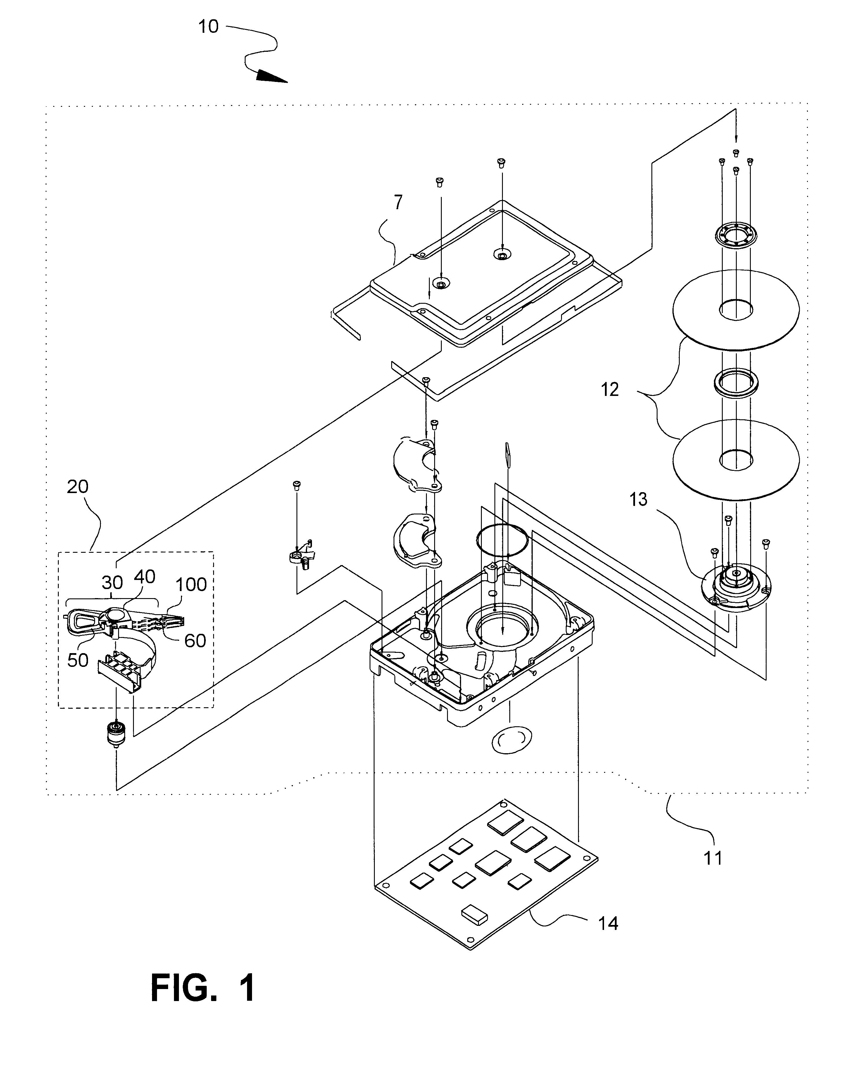
FIG. 1 shows the principal components of a disk drive 10 in which a position signal construction according to this invention may be implemented. The disk drive 10 comprises a head disk assembly (HDA) 11 and a controller circuit board 14.

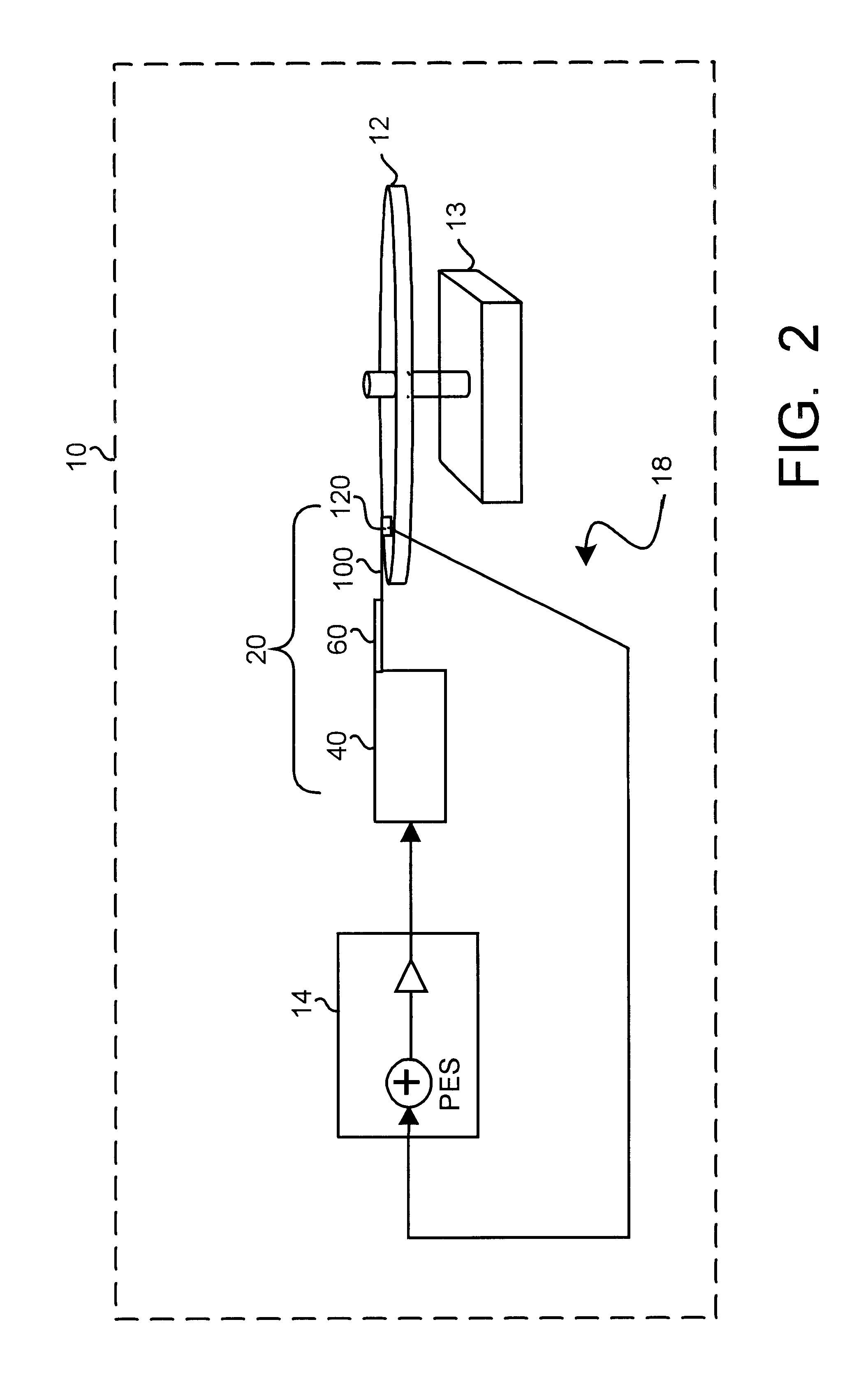
The HDA 11 of FIG. 1 comprises a magnetic disk 12 (2 shown), a spindle motor 13 for rapidly rotating the disk 12, and a head stack assembly 20 located next to the disk 12. The head stack assembly 20 comprises a swing-type actuator assembly 30 having a voice coil 50, an actuator body 40, and an actuator arm 60. At least one head gimbal assembly 100 extends from each actuator arm 60 and carries a transducer head 120 (see FIG. 2) over the disk 12.

The head stack assembly 20 is located so that the head 120 of the head gimbal assembly 100 is biased towards and moveable over the disk 12. The HDA's storage capacity may be increased, as shown in FIG. 1, by including several disks 12 and a head stack assembly 20 having a vertical "stack" of head gimbal assembl...


PUM

PropertyMeasurementUnit
frequencyaaaaaaaaaa
plaaaaaaaaaa
sizeaaaaaaaaaa

Abstract

A method for constructing and linearizing a position error signal (PES) derived from primary and quadrature servo burst pairs in an embedded servo disk drive. The construction method mathematically provides predetermined transition values at the commutation positions connecting adjacent PES segments so that the overall, indicated position signal is numerically continuous from segment to segment. The linearization method compensates for nonlinearity in the PES segments, and thereby in the indicated position signal, without affecting the predetermined transition values at all, or by modifying the predetermined transition values while maintaining continuity.

Description

1. Field of the InventionThe invention relates generally to magnetic disk drives capable of constructing an indicated position signal from an integer track component and a fractional track component or fractional PES segment. The invention relates more particularly to a method of constructing an indicated position signal that is continuous from fractional PES segment to fractional PES segment and a related method of linearizing the fractional PES segments without destroying the continuity.2. Description of the Related ArtA conventional disk drive has a head disk assembly ("HDA") including at least one disk ("disk"), a spindle motor for rapidly rotating the disk, and a head stack assembly ("HSA") that includes a head gimbal assembly (HGA) with a transducer head for reading and writing data. The HSA forms part of a servo control system that positions the transducer head over a particular track on the disk to read or write information from that track.The industry presently prefers a "r...

Claims


Application Information

Patent Timeline
Patent Type & Authority Patents(United States)
IPC IPC(8): G11B5/596
CPCG11B5/59655
Inventor ASGARI, SAEEDHAGEN, MARK D.
Owner WESTERN DIGITAL TECH INC
Why Eureka
Try Eureka