System of supporting bars for use in goods and services establishments

a technology for supporting bars and establishments, applied in the field of supporting bars for use in, can solve the problems of not meeting all the various requirements, the range of known supporting bars is not large enough, etc., and achieves the effects of simple changeover, fixed reliably, and straightforward configuration

Inactive Publication Date: 2002-04-16
VISPLAY IP
View PDF17 Cites 40 Cited by
  • Summary
  • Abstract
  • Description
  • Claims
  • Application Information

AI Technical Summary

Benefits of technology

In summary, it should be stated that the prior range of known supporting-bar arrangements--comprising a plug-in receiving means and a support bar with a plug-in plate seated at the plug-in end or with an internal latching mechanism--still do not satisfy all the various requirements. The problem on which the invention is based is thus to propose a different type of supporting-bar arrangement, of which the support bar requires neither a plug-in plate nor an internal latching mechanism at the plug-in end; rather, it is solely the shaping at the plug-in end which fixes the support bar reliably, on a temporary basis, in the complementary plug-in sleeve, but such that it can also be removed again without difficulty, with the result that an area with numerous plug-in sleeves is straightforward to change round. In particular, the aim is also to make smaller dimensions of the components possible.
Furthermore, it is also intended to be possible for the support bar, which is used in conjunction with the plug-in receiving means, also to be capable of being plugged with arresting action directly into a hollow support. It is also necessary for support bars which are plugged in directly in this way to be capable of being installed, exchanged and removed easily and quickly. It is necessary for the plugged-in support bars to have a sufficient load-bearing capacity and also to be arrested reliably for a lot of activity taking place round about. A large number of possible variations and combinations and a design which satisfies shop-construction requirements are desirable. Finally, the intention is for the supporting-bar arrangements to be capable of being mass-produced at efficient cost.
In a second embodiment, there is arranged in the plug-in sleeve a spring element which projects into the plug-in opening and latches into the hook contour as the support bar is pushed in. The plug-in sleeve preferably has a positioning flange at the front, while a threaded section is provided at the rear. The plug-in sleeve is usually inserted into a bore in a panel, with the result that the positioning flange can be supported on the front side of the panel, on the border of the bore. On the rear side of the panel, a lock nut is screwed to the projecting threaded section. In both variants, it is advantageous for the plug-in opening in the plug-in sleeve to be provided with a minimal upward sloping relation to the horizontal, with the result that the plugged-in support bars are plugged in the plug-in sleeves with a slight inclination and the adverse visual impression of the support bars hanging down askew is avoided in each case.
The invention, then, makes available a further type of supporting-bar arrangement where the support bar has a plug-in of very straightforward configuration and is nevertheless fixed reliably in the plug-in sleeve, or directly in a hollow profile, but can also be changed over straightforwardly. The latching connection produced between the plugged-in support bar and the plug-in sleeve or the hollow profile, then, makes it possible to produce the components in smaller dimensions, which is advantageous in design terms for certain applications. By virtue of the design, laborious adjustment of individual plug-in receiving means within a multiplicity thereof is dispensed with. With correct production and installation, the inserted support bars are aligned precisely of their own accord and thus also provide a solid appearance on the display wall, within the rack or on the relevant fitting. The supporting-bar arrangement can be used in a very varied manner as an actual goods carrier and for securing goods carriers.

Problems solved by technology

In summary, it should be stated that the prior range of known supporting-bar arrangements--comprising a plug-in receiving means and a support bar with a plug-in plate seated at the plug-in end or with an internal latching mechanism--still do not satisfy all the various requirements.

Method used


Image

  • System of supporting bars for use in goods and services establishments
  • System of supporting bars for use in goods and services establishments
  • System of supporting bars for use in goods and services establishments

Examples


Embodiment Construction

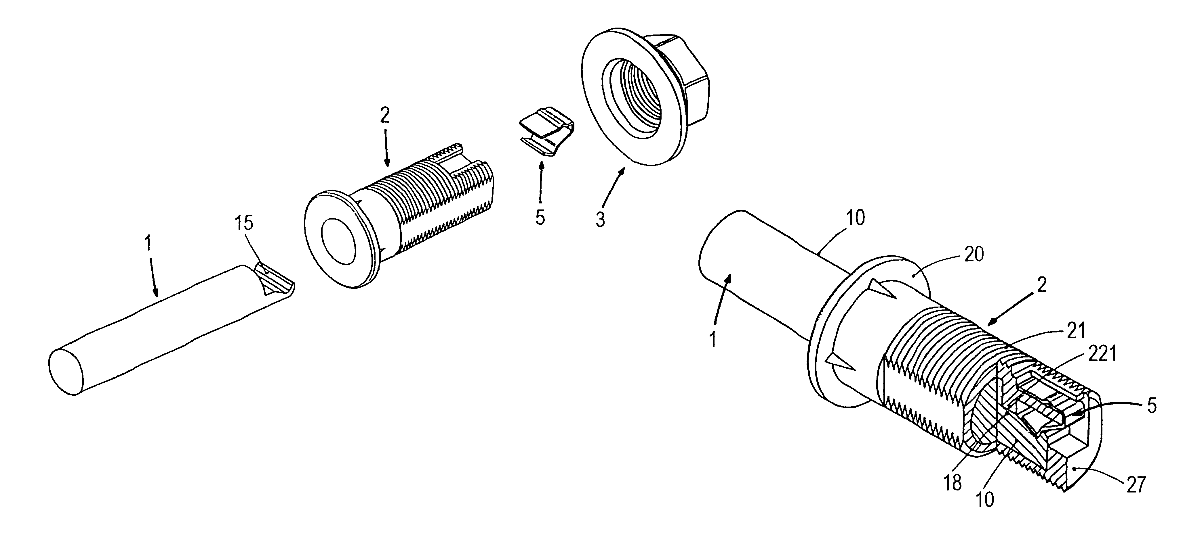
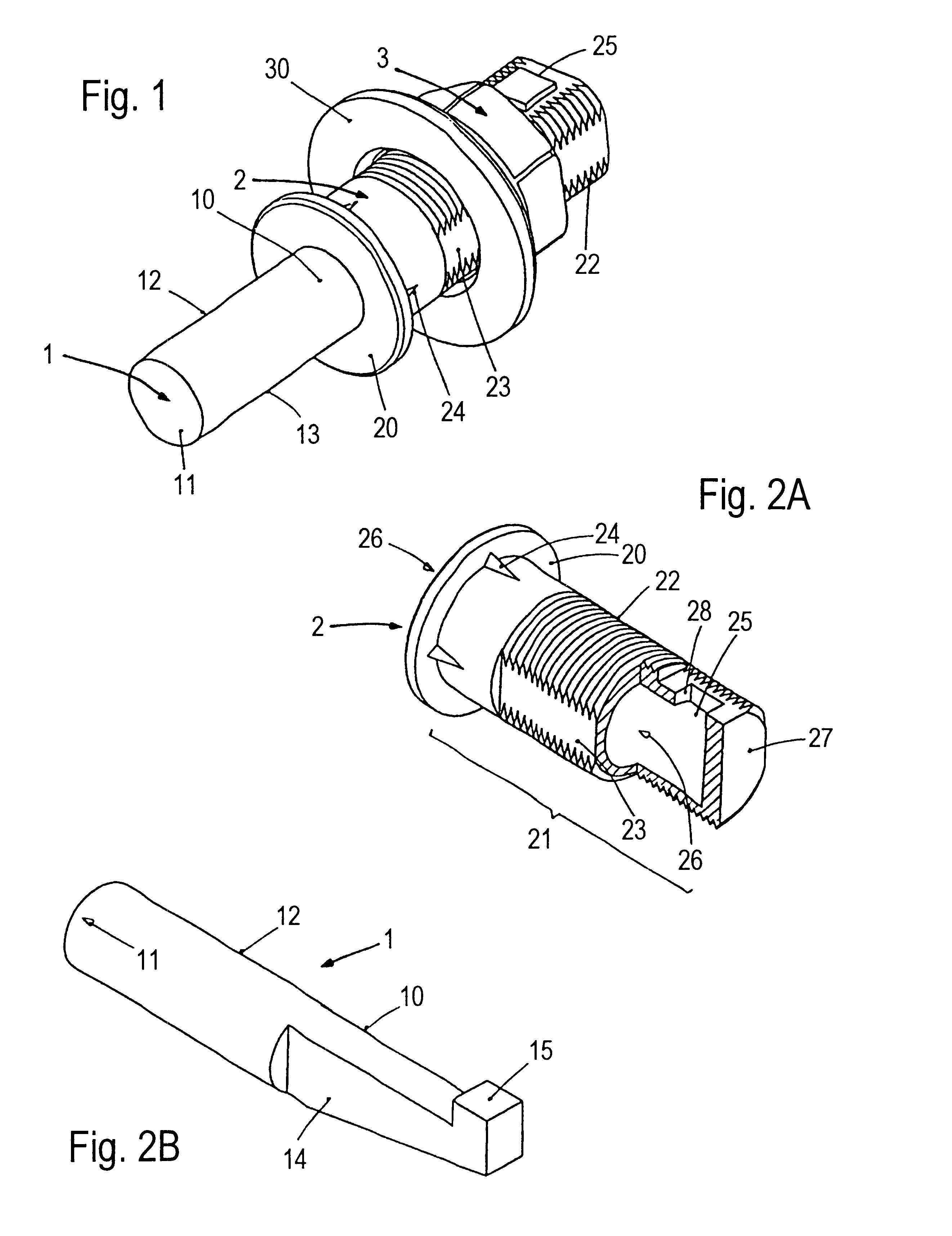
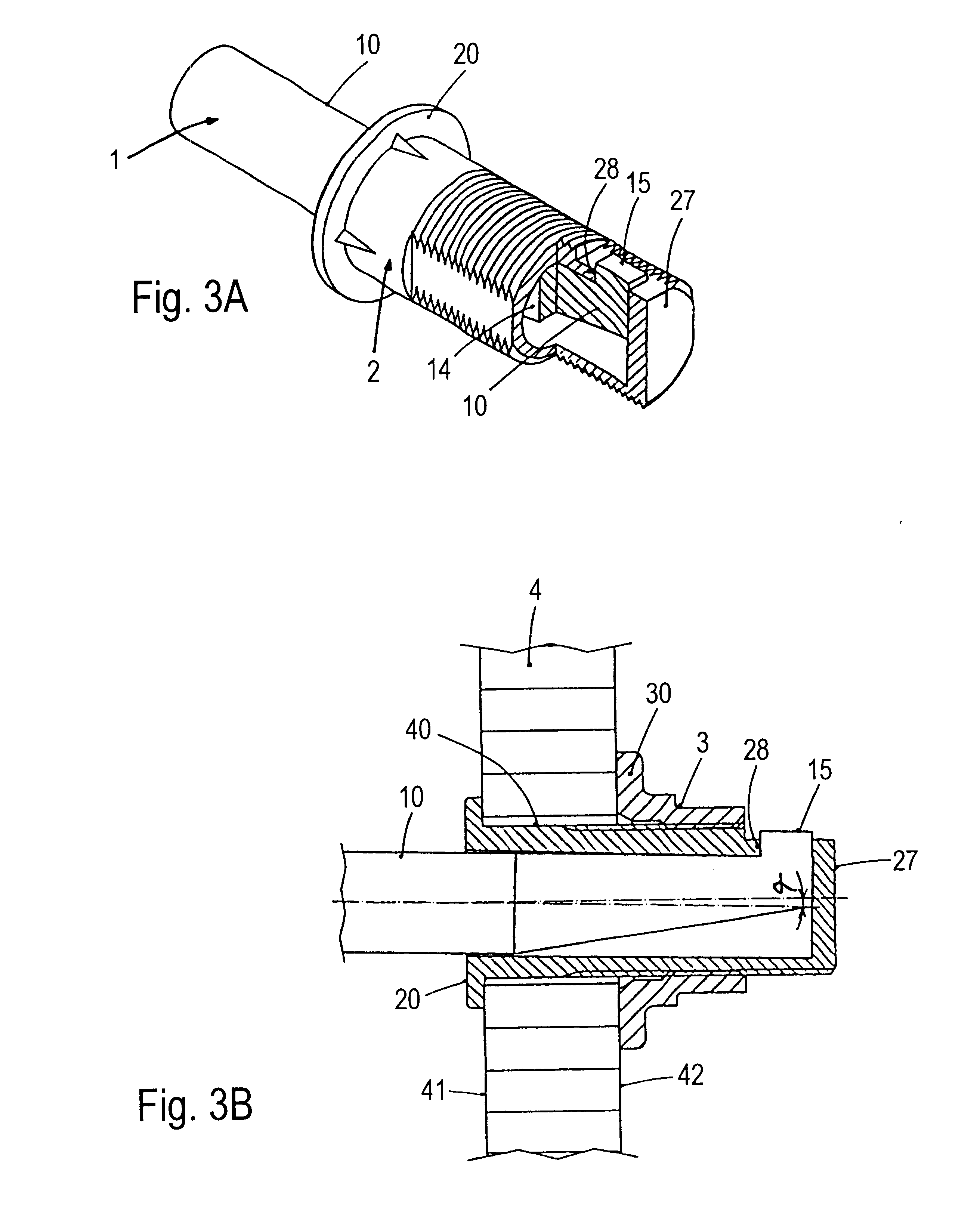
The detailed description of exemplary embodiments of the supporting-bar arrangement according to the invention are given hereinbelow. FIGS. 1 to 3B relate to the first exemplary embodiment, FIGS. 4A to 8B concern second exemplary embodiment, and FIGS. 9A to 13E contain a third exemplary embodiment FIG. 10 constitutes a crossover between the second and third exemplary embodiments. Possible modifications are mentioned following the description.

The following applies to the rest of the description. If, in order to avoid ambiguity in the drawings, a figure contains designations which are not explained in the directly associated text of the description, then you are referred to the point at which they are mentioned in previous or following descriptions of the figures. For reasons of clarity, components are not usually designated again in subsequent figures, provided that it is clear from the drawings that they are "recurring" components.

FIG. 1

The supporting-bar arrangement includes first ...


PUM


Abstract

The supporting-bar arrangement serves for hanging, directly or indirectly, articles which are to be displayed in goods and services establishments. A fundamental constituent part is formed by a support bar which has, at the front, a plug-in end which can be plugged with arresting into an axial inlet opening in a plug-in sleeve or directly into an inlet opening in a supporting structure. The plug-in sleeve is fixed in a through-passage of the supporting structure. A hook contour is provided at the plug-in end, and the plugged-in support bar is arrested in different ways, A spring element is provided in the plug-in sleeve for latching the hook contour of the support bar when the support bar is plugged into the axial inlet opening. The support bar itself serves for hanging articles, or a goods carrier is secured on one or more support bars. The supporting-bar arrangement extends, in particular, the individual and high-quality design possibilities in the construction of shops and trade fairs.

Description

The invention relates to a supporting-bar arrangement having a support bar which can be plugged securely into a supporting structure with or without a plug-in sleeve arranged therein. Possible supporting structures are, in particular, panels, rear walls and supports. Such supporting-bar arrangements are typically used in shops and exhibitions for displaying goods or services, However, the supporting-bar arrangements can also be used for fastening decoration or screening elements and as a mount for information carriers. The articles which are being carried, such as items of clothing, accessories and packed goods, may be hung directly on the support bar or else the support bar forms the bracket for the actual carrier, e.g. a goods rack provided on one or more support bars. Thus, such support bars may be, for example, clothes rails or hangers with one or more arms. It Is possible for the support bars to support shelves, secure information or decoration elements and also retain, for exa...

Claims


Application Information

Patent Timeline
Patent Type & Authority Patents(United States)
IPC IPC(8): A47F5/10A47F5/14A47F5/13F16B9/00F16B9/02
CPCA47F5/10A47F5/14A47F5/137F16B9/023F16B9/056F16B9/054
Inventor WALTER, HERBERTUECKER, MANFRED
Owner VISPLAY IP
Why Eureka
Try Eureka