Current limiting device and circuit interrupter having a current limiting function

a current limiting device and circuit interrupter technology, applied in circuit-breaking switches, circuit-breaking switches for excess currents, protective switch details, etc., can solve the problems of high possibility of insulation breakdown at the wall surface, difficult for the current limiting element portion, and complex structur

Inactive Publication Date: 2002-04-16
MITSUBISHI ELECTRIC CORP
View PDF5 Cites 39 Cited by
  • Summary
  • Abstract
  • Description
  • Claims
  • Application Information

AI Technical Summary

Benefits of technology

The arrangement may be such that the cylindrical insulator comprises in an inner wall surface defining the cy

Problems solved by technology

Also, the movable contacts apt to get into contact with the cylindrical wall surface, resulting in a high possibility of insulation breakdown at the wall surface.
For these reasons, it is difficult for the current limiting element portion alone to obtain a current interrupting function and it is necessary to additionally provide an interruption portion having a current interrupting function.
Therefore, the overall size of the circuit interrupter becomes large, the structure becomes complex and the cost becomes high.
In such the circuit interrupter of high impedance, a high current carrying loss and an abnormal temperature rise due to the current carrying may easily be generated.
Therefore, when a large current carrying capacity is required, such the conventional circuit interrupter cannot be used.
Therefore, when there is a limit in the dimension in the direction of movement of the movable member, a sufficient separating distance cannot be ensured and the high pressure cannot be effectively related to the arc voltage increase.
Also, when the high pressure could not be effectively related to the arc voltage increase, unnecessary pressure rise is generated, resulting in a problem that a very high housing strength is needed for suppressing the pressure rise.
Also, in the current limiting device shown in FIGS. 149 to 1

Method used


Image

  • Current limiting device and circuit interrupter having a current limiting function
  • Current limiting device and circuit interrupter having a current limiting function
  • Current limiting device and circuit interrupter having a current limiting function

Examples


embodiment 1

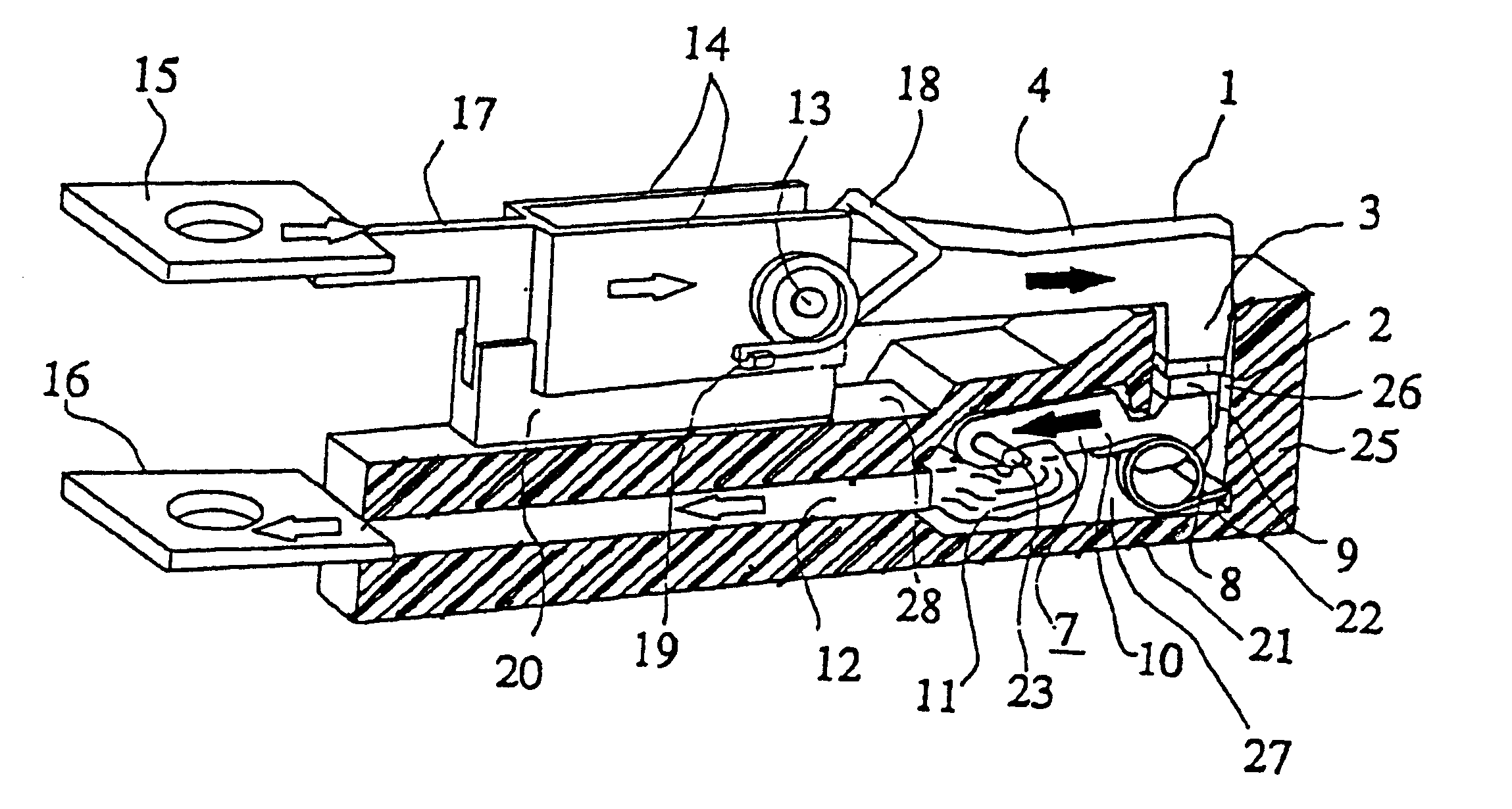
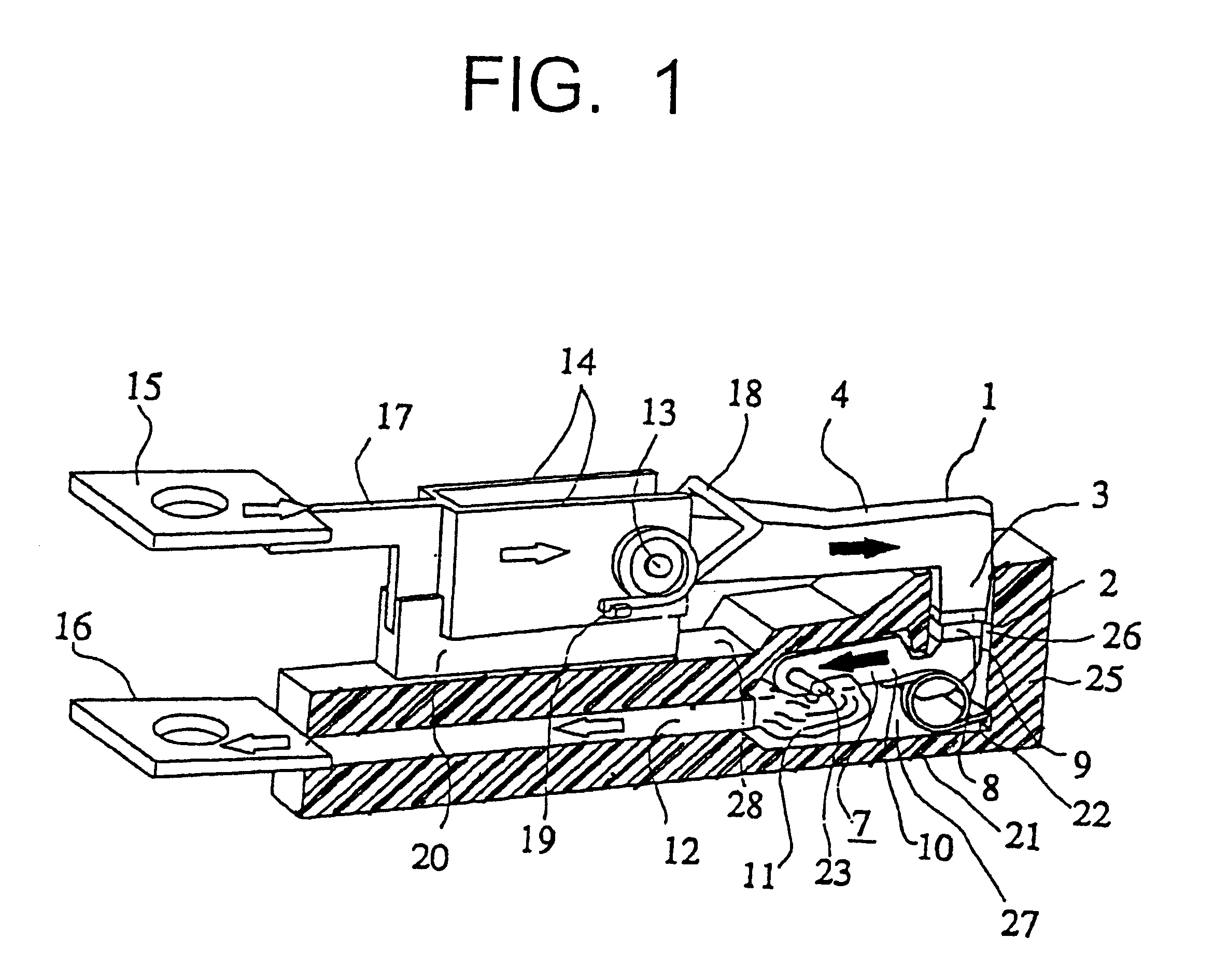
The first embodiment of the present invention will now be described in conjunction with FIG. 1. FIG. 1 is a perspective view showing the main portion of a circuit interrupter according to the first embodiment in the contact closed state, with one portion of a cylindrical insulator 25 and an insulating cover 28 which is an electrical insulator covering the stationary conductor 12 is removed for illustrating the internal structure. In FIG. 1, 1 is a movable member of substantially L-shape having a movable contact 2 and a movable arm vertical portion 3 to which the movable contact 2 is secured and a movable arm horizontal portion 4 substantially perpendicular to the movable arm vertical portion 3. The movable member 1 forms one contact pair together with a repulsive member 7 composed of a repulsive contact 8 and a repulsive arm vertical portion 9 and a repulsive arm horizontal portion 10, the movable member 1 and the repulsive member 7 are biased in the contacting direction to each oth...

embodiment 2

The second embodiment of the present invention will now be described in conjunction with the figure. FIG. 9 is a fragmental sectional view showing the main portion such as the cylindrical insulating material 25, the repulsive member 7, the movable member 1 and the like of this embodiment, and in the figure, a locus drawn during the contact separating movement by the point of the movable member 1 most remote from its rotating center is depicted by a dot-and-dash line, and a locus drawn during the contact separating movement by the point of the repulsive member 7 most remote from its rotating center is depicted by a dash line. The surface portions of the cylindrical insulating material 25 that oppose to the tip portions of the movable member 1 and the repulsive member 7 are configured into an arc-shape to maintain a constant clearance with respect to the dot-and-dash line and the broken line. Generally, the rotary shaft 13 of the movable member 1 is disposed above the contact contacti...

embodiment 3

The third embodiment of the present invention will now be described in conjunction with the figure. FIG. 10 is a fragmental sectional view illustrating the main portion such as the cylindrical insulating material 25, the repulsive member 7, the movable member 1 and the like of this embodiment, the cylindrical insulating material 25 being composed of an insulating material 25a defining a cylindrical inner surface and a surrounding insulating material 25b around the material 25a. The insulating material 25a is a mold made of a material that emits a large amount of vapor immediately when exposed to the arc, such as a resin material including only a small amount of or no reinforcing material such as glass fibers, and the insulating material 25b is made of an reinforced resin or a ceramic superior in mechanical strength. With this structure, a material that cannot mechanically endure the elevated pressure within the cylinder can be used as a material for defining the cylinder inner surfa...


PUM


Abstract

A current limiting device includes first and second contact members, each contact member having, at a first end, contacts defining a contact pair; a contacting pressure is applied to said contact pair; and a cylindrical insulator cylindrically surrounding the contacts when the contacts are closed. The device is arranged such that at least one of the first and second contact members is rotatably supported at a second end. Also, an electrical path is defined through which currents flow in substantial opposition to the first and second contact members and in opposite directions to each other. The first ends of the first and second contact members are positioned within the space defined by the cylindrical insulator in the closed contact state. The contact of at least one of the rotatably supported contact members is positioned outside of the space defined by the cylindrical insulator when the contacts are open.

Description

This invention relates to a current limiting device and a circuit interrupter having a current limiting function.FIG. 147 is a perspective view and a partial sectional view showing a conventional circuit interrupter disclosed for example in Japanese Patent Publication No. 1-43973, in which 1130 is a current limiting element portion connected in electrically series to the interrupter portion 1140 by a conductor 1290, 1001 is a movable member of the current limiting element portion 1130 having a support member 1711 including a movable contact 1002 and a magnetic material, 1005 is a stationary member of the current limiting element portion 1130 and having a stationary contact 1006, the movable member 1001 and the stationary member 1005 together constituting a contact pair. 1280 is an excitation coil connected in electrically series to the contact pair, 1018 is a movable member contacting pressure spring for generating a suitable contacting pressure in the contact pair. 1015 is a termin...

Claims


Application Information

Patent Timeline
IPC IPC(8): H01H77/00H01H33/70H01H33/98H01H77/10H01H9/34H01H73/00H01H71/02H01H77/06H01H9/46H01H73/18H01H9/30H01H9/44
CPCH01H33/98H01H77/10H01H9/302H01H9/34H01H9/342H01H9/446H01H9/46H01H2077/025H01H73/18H01H77/06H01H77/107H01H77/108H01H71/0257
Inventor MITSUHASHI, TAKAOTSUKIMA, MITSURUTAKAHASHI, MITSUGUFUSHIMI, MASAHIROFUKUYA, KAZUNORIMURATA, SHIROYAMAGATA, SHINJI
Owner MITSUBISHI ELECTRIC CORP
Why Eureka
Try Eureka