

Occupant protection apparatus
a technology for protecting equipment and occupants, applied in the direction of process and machine control, pedestrian/occupant safety arrangement, instruments, etc., can solve the problem that the above-mentioned estimation method cannot be used for an occupan
- Summary
- Abstract
- Description
- Claims
- Application Information
AI Technical Summary
Benefits of technology
Problems solved by technology
Method used
Image

Examples
first embodiment
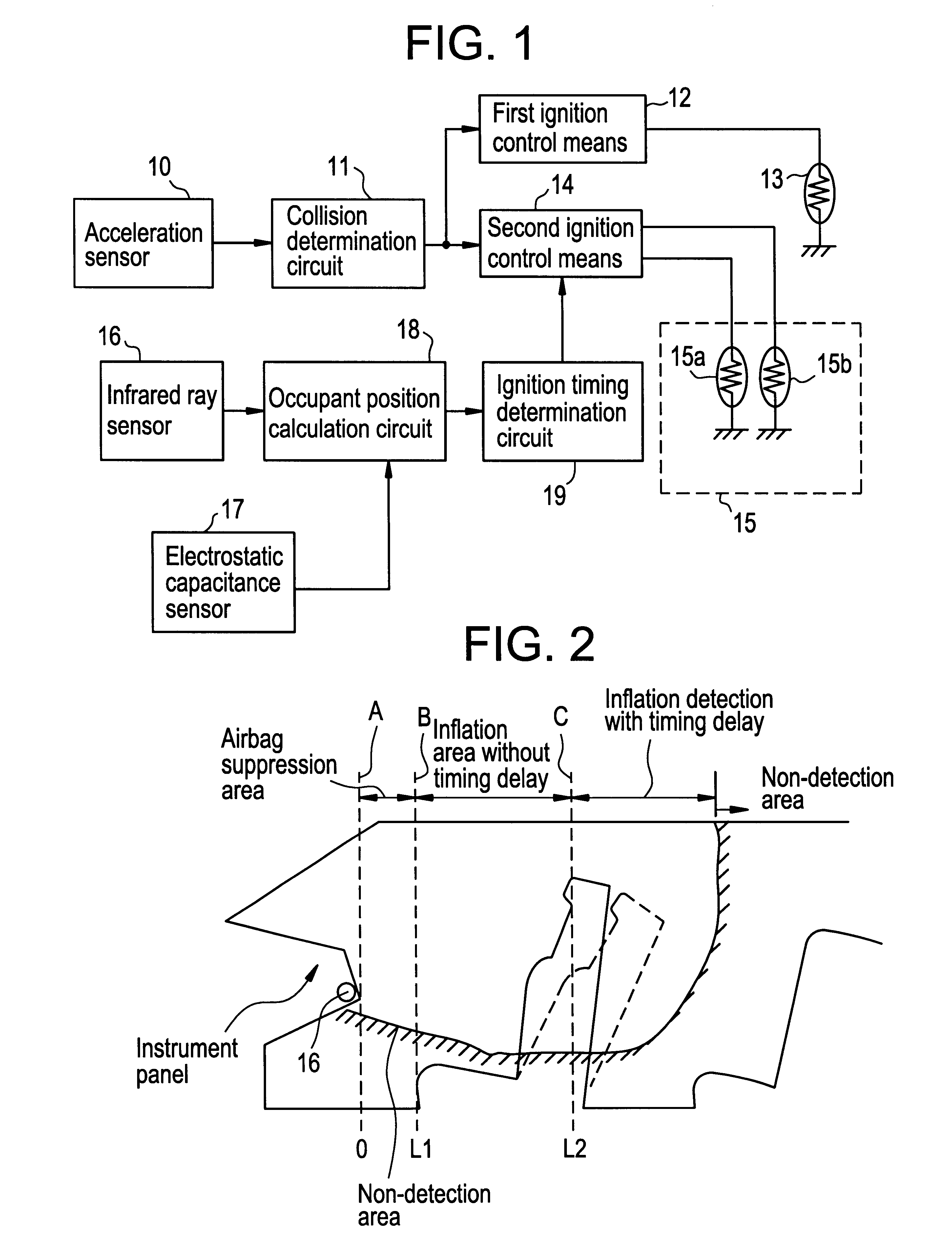
The occupant protection apparatus according to the present invention will be explained with reference to FIG. 1.
In FIG. 1, a reference numeral 10 depicts an acceleration sensor which detects a magnitude of acceleration generated along the longitudinal direction (that is, front and rear direction) of a vehicle and outputs an acceleration signal representing a magnitude of the detected acceleration. A reference numeral 11 depicts a collision determination circuit which receives the acceleration signal supplied from the acceleration sensor 10 to determine the magnitude of the collision, and outputs an ignition signal in accordance with the determined magnitude of the collision. A reference numeral 12 depicts a first ignition control circuit which supplies an ignition current to a driver seat side detonator 13 in response to the ignition signal supplied from the collision determination circuit 11 to inflate an air bag provided at a steering. A reference numeral 14 depicts a second ignit...
second embodiment
The occupant protection apparatus according to the present invention will be explained with reference to FIGS. 5 and 6. In these figures, portions identical to those of FIGS. 1 and 3 are referred to by the common symbols, with explanation thereof being omitted. As shown in FIG. 5, an integration circuit 118 is further provided in this embodiment.
The integration circuit 118 integrates twice the acceleration signal supplied from the acceleration sensor 10 to calculate an amount of deviation of the head of an occupant at the time where the acceleration is applied to the head of the occupant. The integration circuit 118 may be arranged by serially connecting two primary integration circuits. Alternately, an amount of the deviation may be estimated by using a circuit arranged to operate as shown in FIG. 7.
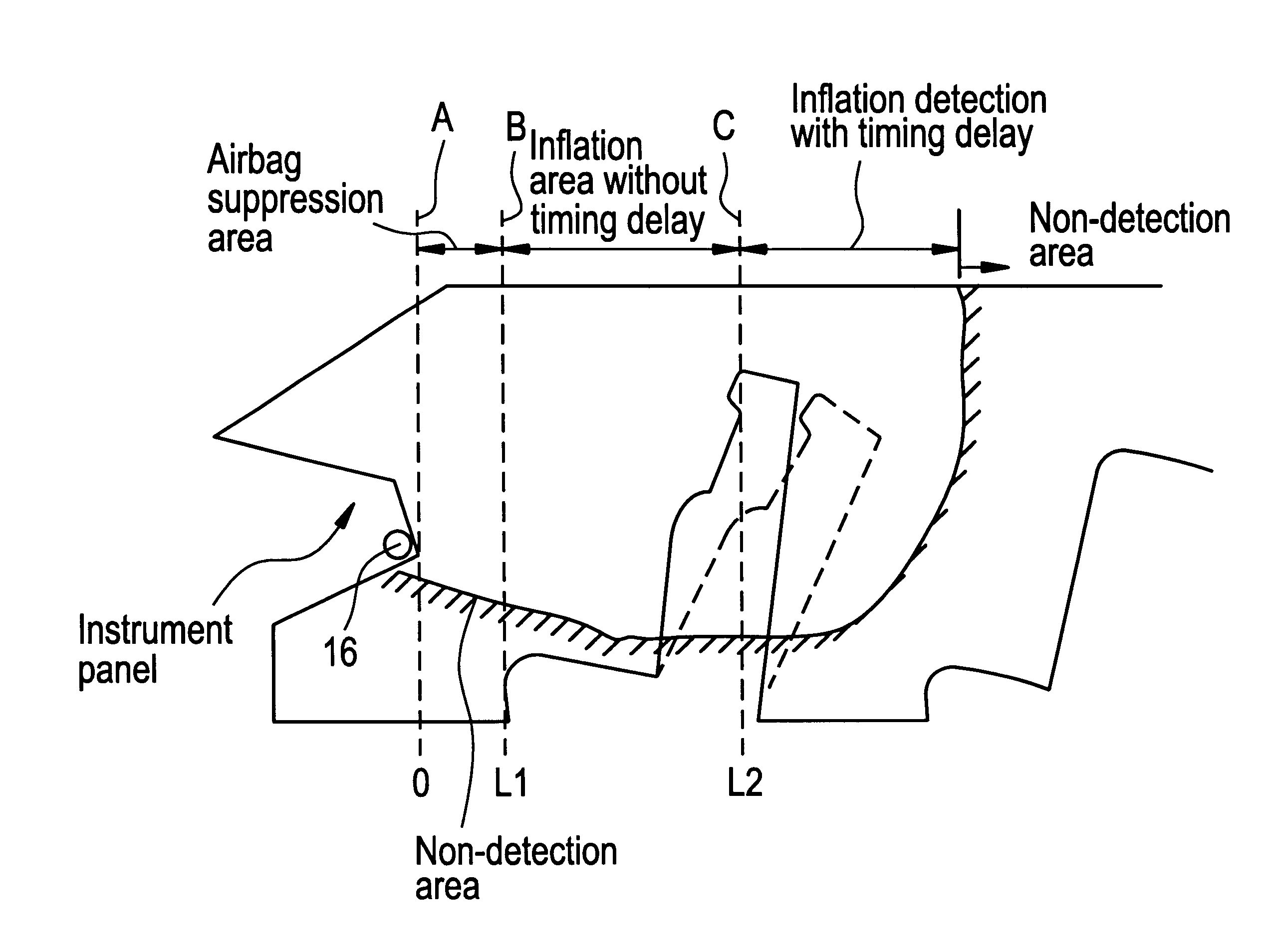
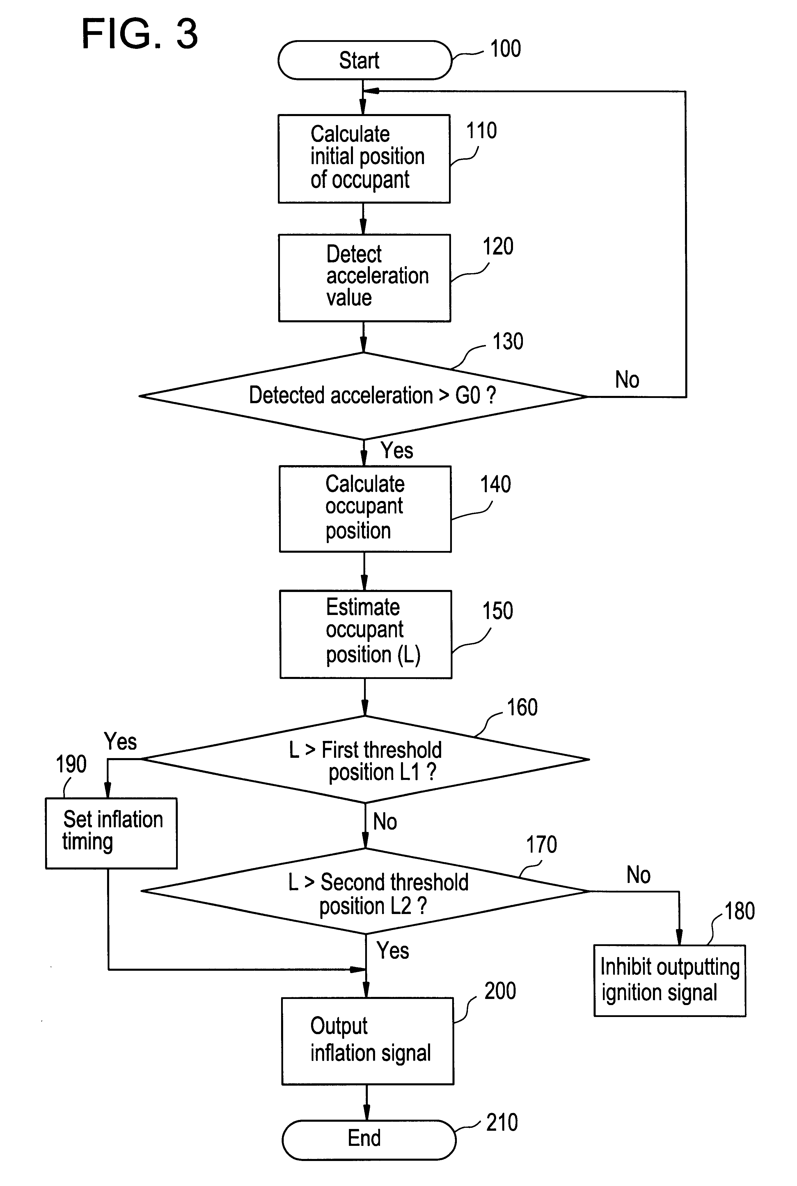
A reference numeral 18 depicts an occupant position calculation circuit which determines whether or not an occupant is sitting on the passenger seat on the basis of the output from the ...
PUM
 Abstract
Description
Claims
Application Information