
Apparatus and method for driving a plurality of induction motors

a technology of induction motors and apparatuses, applied in the direction of motor/generator/converter stoppers, multiple dynamo-motor starters, dynamo-electric converter control, etc., can solve the problems of severe overload of the motor driver 12, unsuitable for providing voltage and current to a plurality, and the conventional configuration of providing drive power shown

Inactive Publication Date: 2002-04-16
BAE SYSTEMS CONTROLS INC +1
View PDF5 Cites 71 Cited by
  • Summary
  • Abstract
  • Description
  • Claims
  • Application Information

AI Technical Summary

Problems solved by technology

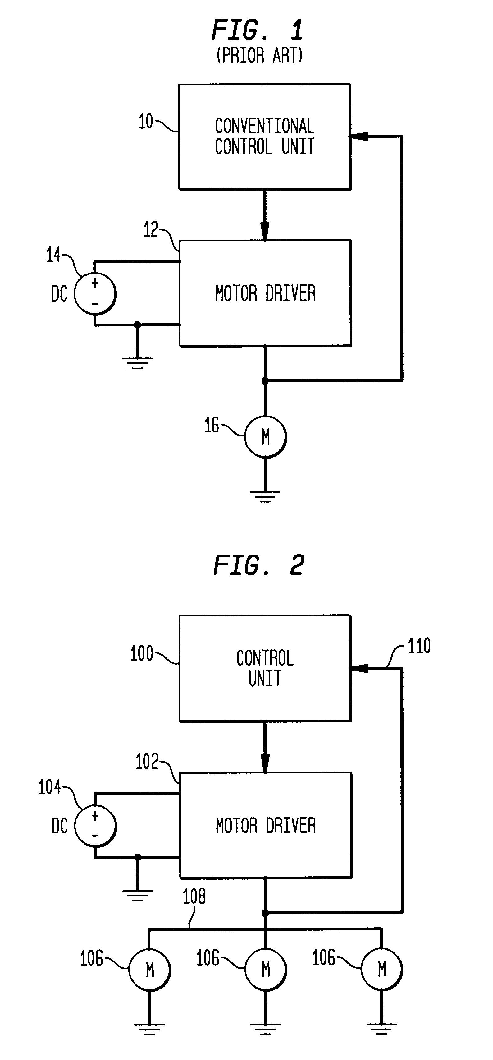
Unfortunately, the conventional configuration for providing drive power shown in FIG. 1 is unsuitable for providing voltage and current to a plurality of induction motors over a single bus, particularly when some of the induction motors are rotating and others of the induction motors require high start-up currents.
Furthermore, even if stopping all the induction motors were acceptable (which is often not the case) a current overload during start-up could cause a positive feedback condition resulting in severe overload of the motor driver 12.
This has the unfortunate effect of increasing (not decreasing) the current drawn by the induction motors.
The conventional control unit 10 might then attempt to further reduce the voltage in the induction motors, thereby creating a positive feedback condition and eventually critically overloading the motor driver 12.
Unfortunately, this would require sizing electronic components within the motor driver 12 to handle currents which are orders of magnitude greater than might otherwise be required during normal operation.

Method used


Image

  • Apparatus and method for driving a plurality of induction motors
  • Apparatus and method for driving a plurality of induction motors
  • Apparatus and method for driving a plurality of induction motors

Examples


Embodiment Construction

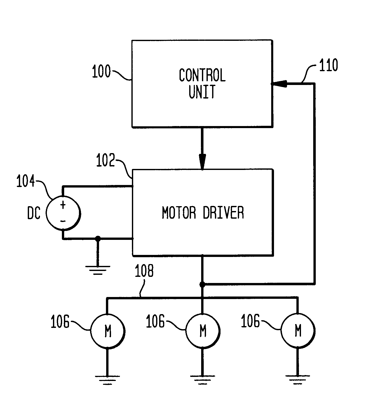
Referring now to the drawings, wherein like numerals indicate like elements, there is shown in FIG. 2, an apparatus for providing voltage and current to a plurality of induction motors 106 in accordance with one aspect of the present invention. The apparatus includes a control unit 100, a motor driver 102 (which receives voltage from a source 104), and the plurality of induction motors 106 which receive voltage and current from the motor driver 102 over a common bus 108. In accordance with one aspect of the present invention, the control unit 100 is operable to monitor the current drawn from the driver stage 102 by way of current sense path 110.

The apparatus is preferably capable of providing start-up current to at least one of the induction motors 106 while one or more others of the induction motors 106 are already rotating. To this end, the control unit 100 is preferably operable to monitor the current drawn from the driver stage 102 and cause one or more of the induction motors 1...


PUM


Abstract

A motor controller includes: a driver stage operable to provide voltage and current to a plurality of induction motors over a single power bus; and a control unit operable to monitor the current drawn from the driver stage and cause one or more of the induction motors to operate in a regenerative mode to supply current to at least one other of the induction motors when the current drawn from the driver stage exceeds a threshold.

Description

1. Field of the InventionThe present invention relates to an apparatus and / or method for providing voltage and current to a plurality of induction motors and, more particularly, operating one or more of the induction motors in a regenerative mode to supply current to at least one other of the induction motors under certain circumstances.2. Related ArtA motor controller is utilized to provide voltage and current to an induction motor. In a normal mode of operation, the voltage and current sourced to the induction motor oscillate at a frequency which (together with a magnitude of the voltage) dictate a speed at which the motor rotates.FIG. 1 illustrates a conventional configuration for providing voltage and current to an induction motor. The conventional configuration includes a conventional control unit 10, which provides command signals to a motor driver 12. The motor driver 12 often receives power from a DC source 14 and converts the DC power to the voltage and current for the indu...

Claims


Application Information

Patent Timeline
Patent Type & Authority Patents(United States)
IPC IPC(8): H02P5/74H02P1/30
CPCH02P5/74
Inventor PETERSON, WILLIAM ANDERSLYONS, ARTHUR PAULL
Owner BAE SYSTEMS CONTROLS INC
Learn More