AC induction motor having multiple poles and increased stator/rotor gap

a technology of induction motor and stator, which is applied in the direction of windings, dynamo-electric components, and magnetic circuit shapes/forms/constructions, etc., can solve the problems of increasing torque, increase the magnetic resistance of the circuit, increase the torque, increase the motor torque

Inactive Publication Date: 2006-01-19
PRATT & WHITNEY POWER SYST +1
View PDF62 Cites 46 Cited by
  • Summary
  • Abstract
  • Description
  • Claims
  • Application Information

AI Technical Summary

Benefits of technology

[0013] The windings can be configured for three phases such that there are thirty-six stator teeth to form twelve poles. Furthermore, the gap between the stator and rotor is configured to increase the magnetic reluctance of the circuit thereby increasing the torque. Alternatively, the motor can be operated in partial saturation in order to increase motor torque.
[0014] Additionally, there is provided a method of making an electric motor with increased torque. The method comprises providing a rotor having a plurality of rotor teeth and a shaft. A stator is provided that has a plurality of stator teeth. The stator is configured to circumferenti

Problems solved by technology

Furthermore, the gap between the stator and rotor is configured to incre

Method used


Image

  • AC induction motor having multiple poles and increased stator/rotor gap
  • AC induction motor having multiple poles and increased stator/rotor gap
  • AC induction motor having multiple poles and increased stator/rotor gap

Examples


Embodiment Construction

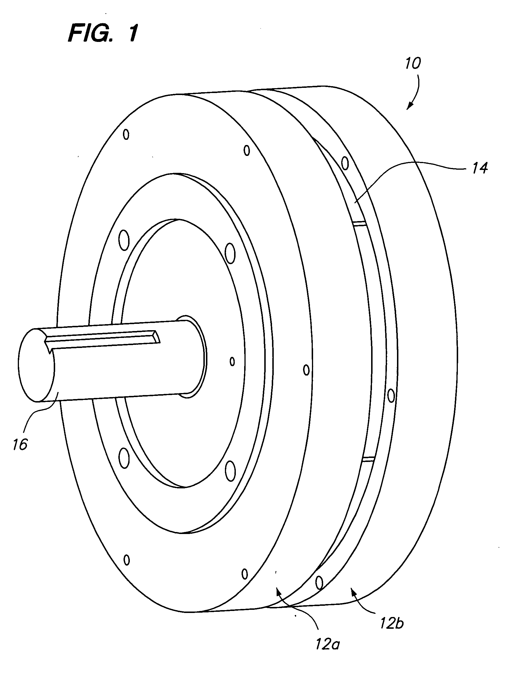
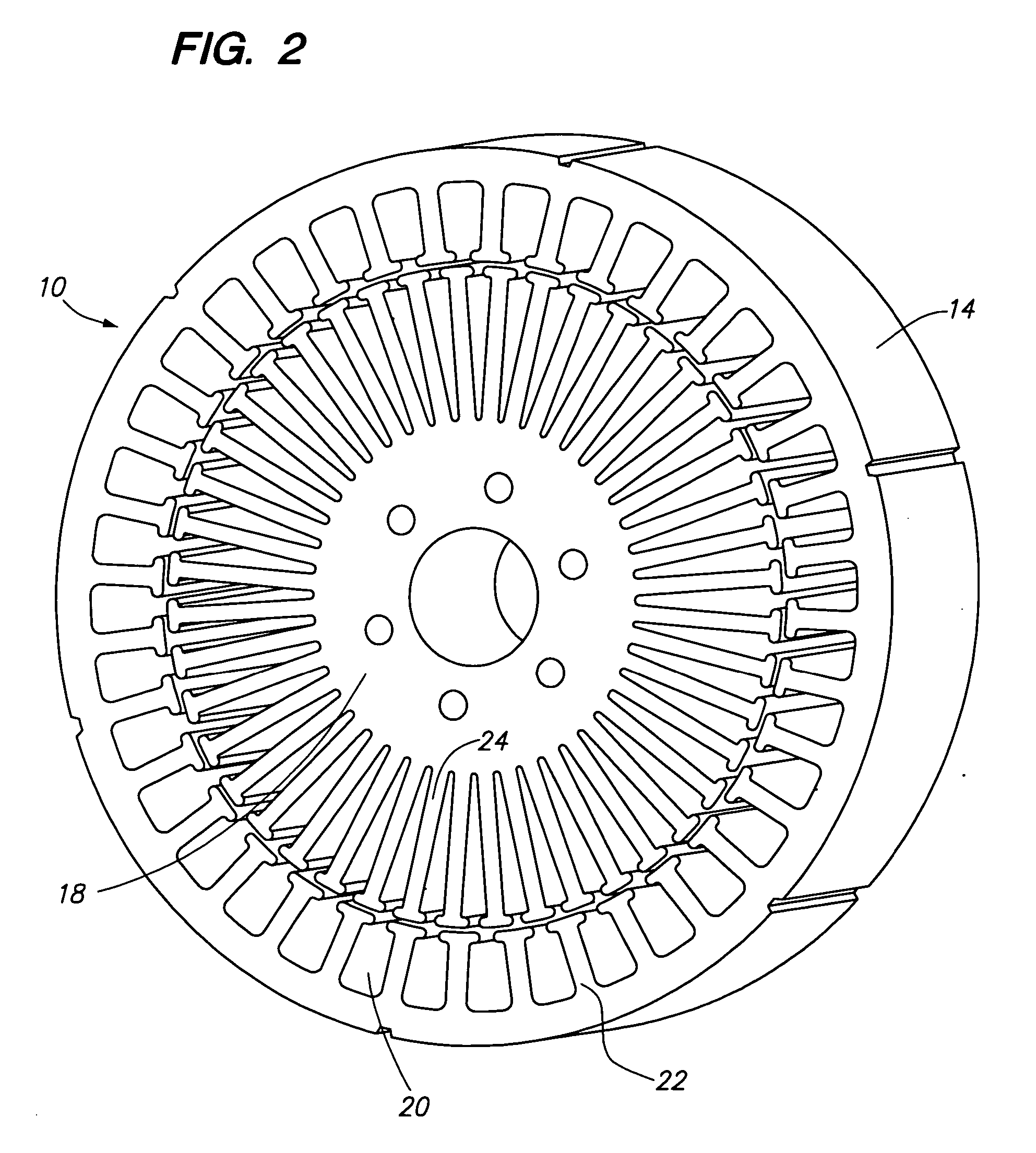
[0024] Referring now to the drawings wherein the showings are for purposes of illustrating preferred embodiments of the present invention only, and not for purposes of limiting the same, FIG. 1 is a perspective view of a multiple-pole, flat form factor motor 10. The motor 10 has two circular end bells 12a, 12b supporting a circular stator core 14. As will be further explained below, the stator core 14 is formed from a metallic material such as iron and contains multiple teeth surrounded by wire windings. A shaft 16 extends from the motor 10 and is attached to a rotor 18, as seen in FIG. 2. The rotor 18 is generally circular and is sized to be inserted within the stator core 14. The rotor 18 has multiple teeth 24 disposed around the circumference thereof. Each of the teeth 24 is surrounded by a wire winding. Similarly, the stator core 14 has multiple winding slots 20 and teeth 22 disposed around an interior circumference. Each of the stator teeth 22 is surrounded by a wire winding. I...


PUM


Abstract

There is provided an electric motor having a flat form factor. The electric motor has a rotor with a shaft attached thereto. The rotor further includes a plurality of teeth disposed thereon. The motor further includes a stator having an axial length. A plurality of teeth are disposed on the stator such that a gap is defined between the teeth of the stator and the teeth of the rotor. The motor further includes a plurality of copper windings disposed around each of the teeth of stator. Each of the windings has a length of end copper equal to about twice the axial length of the stator. In this regard, the end of the wire is greater than the width of the stator such that the form factor of the motor can be flattened.

Description

BACKGROUND OF THE INVENTION [0001] 1. Field of Invention [0002] The present application generally relates to AC induction motors and more specifically to an AC induction motor having increased torque output by increasing the number of poles and increasing the gap between the stator and rotor. [0003] 2. Status of the Prior Art [0004] The theory of motor operation can be developed based on the equivalency of electric-to-magnetic-to-mechanical energy exchange. The theory encompasses both the Lorentz Force Equation and the equation for attractive forces. The Lorentz Force Equation is usually invoked for evaluating AC machine performance while the equation for attractive forces evaluates reluctance motor analysis. [0005] The universal law used to explain the operation of an electromotive machine is simply stated as the equivalence of the change in stored magnetic energy dEmagnetic with the change in mechanical shaft energy dEmechanical: dEmagnetic=dEmechanical   Eq. 1 [0006] where: [0007...

Claims


Application Information

Patent Timeline
IPC IPC(8): H02K17/00H02K1/00H02K3/00
CPCH02K3/18H02K3/12
Inventor KERLIN, JACK H.
Owner PRATT & WHITNEY POWER SYST
Why Eureka
Try Eureka