Apparatus for controlling heat generation and recovery in an induction motor

a technology of induction motor and controller, which is applied in the direction of motor/generator/converter stopper, dynamo-electric converter control, piston pump, etc., can solve the problems of not providing any control over the amount of heating power or heat energy delivered, and water bathing,

Inactive Publication Date: 2006-07-25
SEQUENCE CONTROLS
View PDF7 Cites 49 Cited by
  • Summary
  • Abstract
  • Description
  • Claims
  • Application Information

AI Technical Summary

Problems solved by technology

An issue with bathing appliances, swimming pools and the like is cooling of the bathing water during operation.
The human body is keenly tuned to a very narrow “thermal comfort zone” and straying outside of this area by even a few degrees causes discomfort.
During operation, the electric motor of the recirculation pump has been found to become quite hot, requiring the use of cooling fans mounted as an integral part of the motor design.
Although each of the above prior art designs works more or less effectively than integrated fans to provide supplementary heat and lower motor operating temperature, they do not provide any control over the amount of heating power or delivered heat energy.
In such an example, supplementary heating would be required, rendering the heat recovery system of little heating capacity value.
Such a situation would result in water temperatures rising over time due to excessive heat energy input (heating power multiplied by time operated), perhaps beyond the safe operating limits determined by regulatory agencies and safety organizations.
Should the applied voltage to the motor be lowered while the frequency remains constant, the resulting V / F ratio will also lower resulting in high operating current, lower efficiency and additional heat output.
At some critical point on the V / F ratio curve, in combination with ambient air temperature and mechanical load, motor internal heating will exceed the ability of the internal fan to remove this heat and thermal runaway will occur.

Method used


Image

  • Apparatus for controlling heat generation and recovery in an induction motor
  • Apparatus for controlling heat generation and recovery in an induction motor
  • Apparatus for controlling heat generation and recovery in an induction motor

Examples


Embodiment Construction

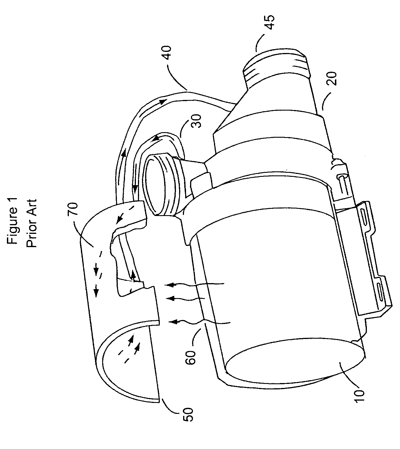
[0039]Referring particularly to the drawings, there is shown in FIG. 1 a prior art embodiment of a heat recovery system which may be retrofit to an existing induction motor. An induction motor 10 is connected to a pump means 20. The heat recovery apparatus 50 is attached to the motor 10 in such a manner as to ensure proper thermal conductivity 60 between the motor 10 and heat recovery apparatus 50.

[0040]During motor / pump operation, pressurized water 30 is delivered to the heat recovery apparatus 50. Water 70 flowing in the heat recovery apparatus 50 absorbs waste heat 60, and delivers heated water through pipe 40 at the low-pressure intake 45 of pump 20. Such systems are known to be inexpensive and simple to retrofit to existing motors, although thermal absorption between the motor and heat recovery apparatus is limited.

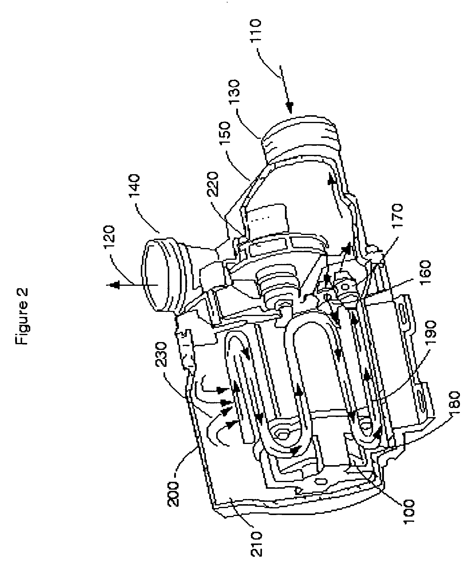
[0041]Referring now to FIG. 2, there is shown an alternative prior art apparatus wherein the heat recovery apparatus is provided as an integral component of the indu...


PUM


Abstract

An induction motor system comprising an induction motor, equipped with a heat recovery and water pumping apparatus and an apparatus for controlling the electrical efficiency and resulting heat generation of the induction motor. The motor is adapted to be coupled to an AC source for supplying an AC signal. The controlling apparatus includes a switching device, user controls and optional inputs. The switching device is connected in series with the motor and is operative in either a high impedance state wherein significant current flow through the motor is prevented or a low impedance state wherein current flow through the motor is substantially undisturbed. The user controls provide motor operational input signals. The optional inputs provide setpoint and sensed water temperature input signals. The controller means receives the motor operational setpoint and sensed water temperature input signals from the user controls and optional inputs, and switches the switching device between its low and high impedance states in a predetermined sequence for inducing a phase delay in the AC signal.

Description

FIELD OF THE INVENTION[0001]The present invention relates generally to an apparatus used to control the electrical efficiency and resulting heat generation of an electrically operated A.C. induction motor. More particularly, the present invention relates to a controller coupled to a switching means and employing a voltage modulation to adjust the efficiency of an induction motor coupled to a heat recovery system.BACKGROUND OF THE INVENTION[0002]Bathing appliances such as hot tubs, swimming pools, shower units and hydromassage bath fixtures employ a means to control the flow of electrical energy to the pump motor, air blower, or other electrical loads associated with their use. The prior art means of providing this control may be very simple, for example a wall mounted switch or mechanical timer may be utilised to turn the circulation pump on and off.[0003]An issue with bathing appliances, swimming pools and the like is cooling of the bathing water during operation. This may be cause...

Claims


Application Information

Patent Timeline
Patent Type & Authority Patents(United States)
IPC IPC(8): H02K23/16H02K23/18H02K23/44H02K37/00
CPCH02P27/16H02K17/30H02K9/19H02K9/00
Inventor KEMP, WILLIAM H.
Owner SEQUENCE CONTROLS
Why Eureka
Try Eureka