Method for cutting and treating vegetation

a technology for cutting and treating vegetation, applied in the direction of digger harvesters, agriculture tools and machines, agriculture, etc., can solve the problems of inability to cut vegetation and treat cut vegetation in a non-horizontal orientation, tube breakage or kink, subject to puncture or torn away, etc., to achieve the effect of not spoiling or losing potency

Inactive Publication Date: 2002-04-23
BURCH CO +1
View PDF8 Cites 16 Cited by
  • Summary
  • Abstract
  • Description
  • Claims
  • Application Information

AI Technical Summary

Benefits of technology

Accordingly, the treatment fluid is continuously available to the cut ends of the remaining stems at the time that the vegetation is cut so that at least about 75-95% of the treatment fluid is absorbed directly into the translocation stream of the plant in near zero time, thereby maximizing the efficacy of the treatment and vastly reducing the required amount of treatment fluid as well as amount of active ingredient.
The mower preferably includes a generally planar mower deck having a central opening therethrough for receiving the cutting blade drive means therein, a pair of generally linear, opposed sides, a generally linear front wall and an arcuate rear wall. At least a portion of the rear wall may include a plurality of short lengths of debris chain for preventing debris, such as loose stones, from being expelled from the underside of the mower deck. The mower is provided with at least one wheel secured to the mower deck for facilitating movement over the ground and for supporting the cutting and treating means at the desired height above the ground. A plurality of upright stanchions are fixed to the top surface of the mower deck for retaining the fluid container means therebetween.
An inlet port and an outlet port is provided on each cell and fitted with the female portion of a double end shutoff fitting. The male portion of the fitting engages the female portion of the fitting to permit treatment fluid to flow from an upper cell to a lower cell, and from the lowermost cell to a bulkhead fitting adjacent the pumping means. A flexible fluid conduit connects the outlet port of each upper cell to the inlet port of the next lowest cell. The flexible fluid conduit from the outlet port of the bottommost cell passes through the pumping means and is connected to a fitting provided on the housing of the cutting blade drive means. Accordingly, the fluid container means is in fluid communication with the cutting blade drive means. The male portion of the fitting which engages the female portion of the fitting in the inlet port of the uppermost cell is connected to an in-line filter and breather cap for venting the fluid container cells to the ambient atmosphere. The filter prevents debris, insects, etc. from entering the system without restricting the entry of ambient air.
The cells are stacked so that the bottommost cell is automatically filled with the treatment fluid from the upper cells as the treatment fluid is applied to the vegetation. Any number of cells may be filled at a remote location so that the treatment fluid is not spilled at the worksite where it may contact workers, contaminate the surrounding soil or the underground water supply. The cells are hermetically sealed so that the treatment fluid will not spoil or lose potency. A predetermined number of pre-filled cells may be stacked so that the user need not interrupt the cutting and treating operation to refill cells or to replace empty cells. The emptied cells are returned to a formulator for refilling without the need for rinsing at the treatment site and are never disposed of in public land fills or dumpsters.
The flow control means meters the amount of the treatment fluid which is delivered by the pumping means to the underside of the cutting blade. The flow control means includes a control unit which is electrically coupled to a ground speed detection means. The ground speed detection means includes a sensor for detecting the angular velocity of the rear wheel of the tractor, and thus the estimated ground speed of the mower. In a preferred embodiment, a ground speed detection means is provided adjacent each of the rear wheels of the tractor and the angular velocity of the rear wheels is averaged and multiplied by a correction factor to more accurately estimate the ground speed of the tractor. The control unit is also electrically coupled to a DC stepper drive motor which drives the pumping means so that the desired amount of treatment fluid is applied to the vegetation in the area being treated.

Problems solved by technology

Nevertheless, the treatment fluid may fall onto the ground around the plant, and the vaporized treatment may be carried by the wind onto surrounding land.
In addition, none of these apparatus are capable of cutting vegetation and treating the cut vegetation in a non-horizontal orientation, such as from the end of a hinged boom arm.
The centrifugal force of the rotating blade, however, throws the treatment fluid out from the orifice in droplet form.
The tube, however, may break or kink as the blade bends longitudinally, and is subject to being punctured or torn away if the blade strikes a relatively immovable rock or stump.

Method used


Image

  • Method for cutting and treating vegetation
  • Method for cutting and treating vegetation
  • Method for cutting and treating vegetation

Examples


Embodiment Construction

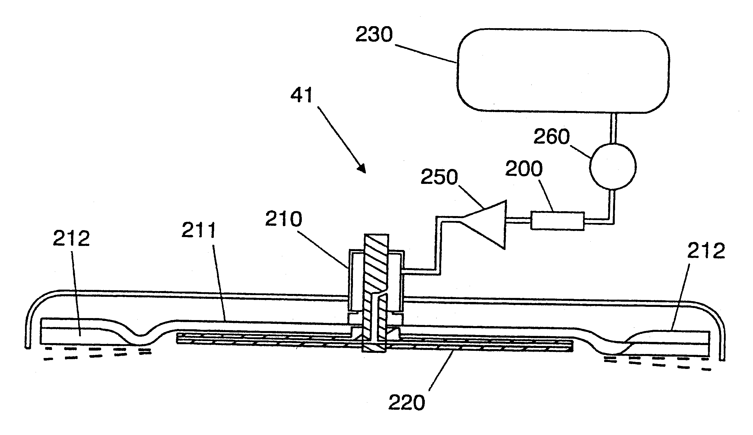
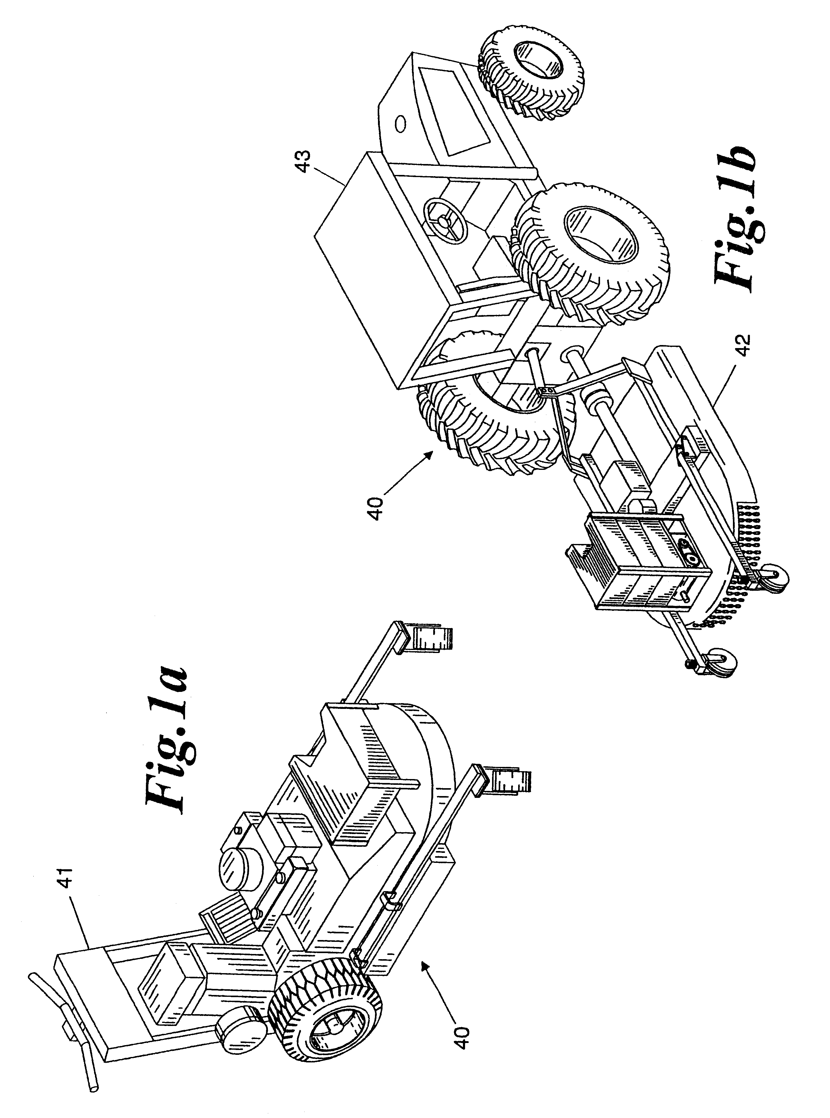
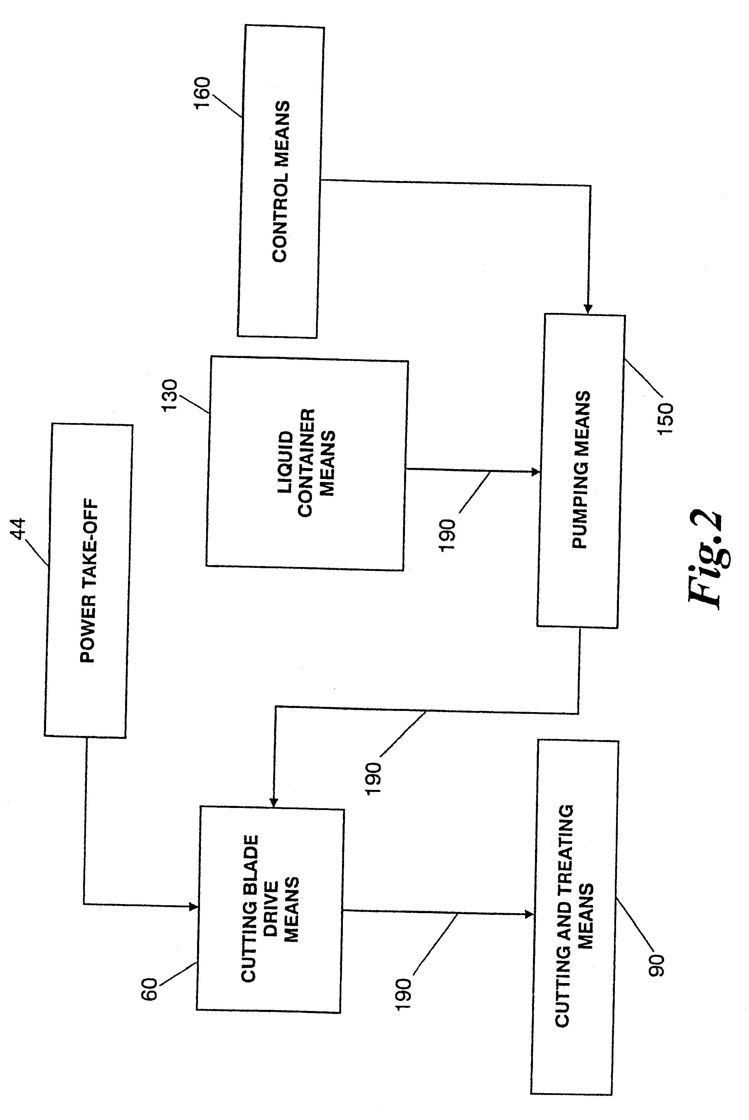
Referring to the accompanying drawings in which preferred embodiments of the invention are shown, FIGS. 1a and 1b illustrate apparatus, indicated generally at 40, for cutting vegetation and simultaneously treating the remaining stems of the cut vegetation with a treatment fluid. The treatment fluid may be any treatment fluid which is applied to vegetation such as a growth regulator, herbicide, pesticide, fungicide, fertilizer or biological agent, depending on the desired result. Preferably, the treatment fluid is water-born. However, the treatment fluid may be born by any substance which combines with the treatment fluid to produce a non-viscous, flowable fluid. The apparatus 40 delivers the treatment fluid to the underside of the cutting blade so that a stream of treatment fluid is continuously available to the remaining stems of the cut vegetation at the time that the vegetation is cut. It has been discovered that a physical phenomenon occurs at the time that vegetation is cut. Fl...


PUM


Abstract

A method for cutting vegetation and simultaneously treating the remaining stems of the cut vegetation with a treatment fluid. In a mower having a cutting blade assembly rotatably mounted on a blade carrier, a treatment fluid in a removable fluid container cells is pumped to the cutting blade. The method includes the steps of cutting vegetation with at least one cutting blade, and delivering a treatment fluid to the underside of the at least one cutting blade in a continuous stream so that the treatment fluid is continuously available to the remaining stems of the cut vegetation. Metering the amount of treatment fluid that is pumped to the cutting blade assembly is precisely controlled at a very low, but effective, rate.

Description

The present invention relates to an apparatus and method for cutting and treating vegetation, and more particularly to an apparatus and method for cutting vegetation while simultaneously applying a treatment fluid to the remaining stems of the cut vegetation.Power companies periodically cut the vegetation that grows along powerline right-of-ways to maintain access to the powerlines and to minimize line losses. Access is required to facilitate service and repair of damaged powerlines. Excessive line losses may occur when high, dense vegetation beneath the powerline causes the electricity flowing through the powerline to bleed into the ground. The higher and more dense the vegetation, the greater the spurious radiation loss from the powerline. Similarly, highway departments periodically cut the vegetation that grows in medians and along roadsides to enhance the safety of motorists and pedestrians. Cutting the vegetation improves visibility and provides a shoulder along the road for em...

Claims


Application Information

Patent Timeline
Patent Type & Authority Patents(United States)
IPC IPC(8): A01D43/00A01D43/14A01D34/64
CPCA01D43/14A01D2101/00
Inventor BURCH, THOMAS B.
Owner BURCH CO
Why Eureka
Try Eureka