Lie-down massager

a massager and lie-down technology, applied in the field of lying-down massagers, can solve the problems of the spring mechanism being too soft to push up the massaging bumps, and achieve the effect of improving the therapeutic

Inactive Publication Date: 2006-03-21
SHIM 30 SIMON K
View PDF14 Cites 19 Cited by
  • Summary
  • Abstract
  • Description
  • Claims
  • Application Information

AI Technical Summary

Benefits of technology

[0004]The present invention is contrived to overcome the conventional disadvantages. Accordingly, an object of the invention is to provide a lie-down massager that improves therapeutic effects by adopting a rack gear mechanism for a vertical movement of massaging bumps.
[0005]Another object is to stabilize the vertical movement of the massaging bumps, thereby enabling patients to receive a steady and robust massaging of the massaging bumps applied to and along their backs and necks. A further object is to improve product reliability and customer satisfaction by mechanically stabilizing the vertical movement of the massaging bumps in accordance with a rack gear construction.
[0009]For a better performance, a rider may have rider guide rollers on each side thereof so the rider guide rollers are rollably engaged to the base frame to guide a horizontally reciprocal movement of the rider. A roller gear is engaged to and powered by a motor fixed to the rider. Here, a pair of pulleys are linked by a rope and respectively mounted in a front end portion and a rear end portion of the base frame where a predetermined portion of the rope is fixedly attached to the rider so that the pulley rotation enables the rider to generate a horizontally reciprocal movement of the rider.
[0010]In order to maximize therapeutic effect, a pair of roller coasters parallel to each other are attached to the base frame and above the rider guide rollers to respectively have a substantially waved top surface. A coasting member having a bottom surface and side surfaces is liftedly engaged to the rider, wherein a support in a substantially cylindrical format is fixedly formed on top of the coasting member where a coaster guide roller is formed outwardly extending from each of the side surfaces of the coasting member so that the coaster guide roller enables the coasting member to make a roller coasting movement on and along the waved top surfaces of the roller coasters while being engagedly lifted from the rider which makes the horizontally reciprocal movement.
[0011]Selectively, a support may be fixedly formed on top of the rider to provide an additional propping to the engagement body to substantially surround the engagement body so as to stabilize the vertically reciprocal movement of the engagement body. A vertical slot may be formed through the support in order for a signal bar to horizontally extend from the engagement body through the vertical slot to controllingly facilitate the vertically reciprocal movement of the lifter. A pair of limit switches respectively formed adjacent to each end of the vertical slot to further facilitate the control of the vertically reciprocal movement of the lifter.
[0012]Advantages of the present inventions include that: (1) the vertical rack gear mechanism minimizes parts required for the vertical movement of the massaging bumps by utilizing the vertical opening through the engagement body and vertical walls formed thereby one of whose wall is configured to a rack gear, while improving stability in the vertical reciprocation of the lifter carrying the massaging bumps; (2) the engagement body downwardly extending from the lifter includes the vertical rack gear therein and props the lifter thereupon while optimally cooperating with the support that detachedly props the engagement body, thereby enhancing product reliability; and (3) the coasting member working with the roller coasters to realize an additional lifting by utilizing the horizontally reciprocal movement of the rider enables the massaging bumps to continue a smooth, steady and robust massaging on the patient, thereby substantially improving massaging effect and subsequently maximizing customer satisfaction.

Problems solved by technology

However, when it comes to therapeutic effects, the spring mechanism proves too soft to push up the massaging bumps when stronger pressure is required, because tension of springs applies equally to patients lying on the massaging device regardless of patient's requirements.

Method used


Image

  • Lie-down massager
  • Lie-down massager
  • Lie-down massager

Examples


Embodiment Construction

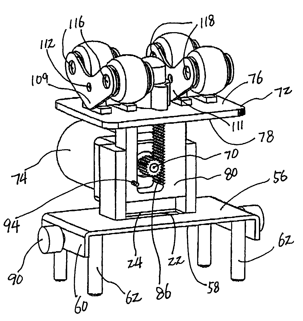
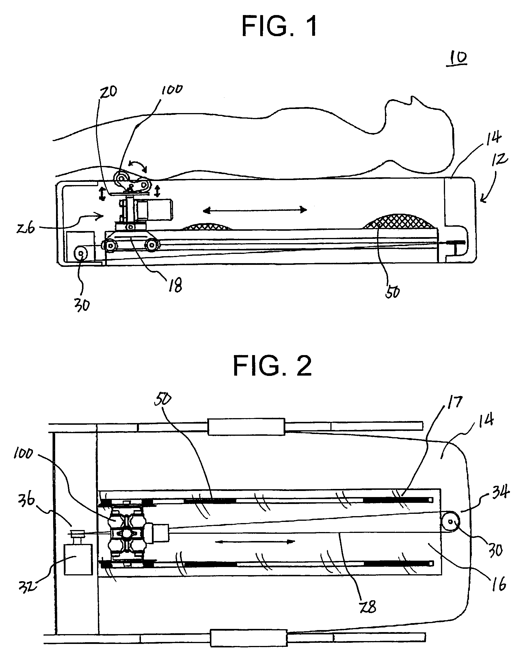
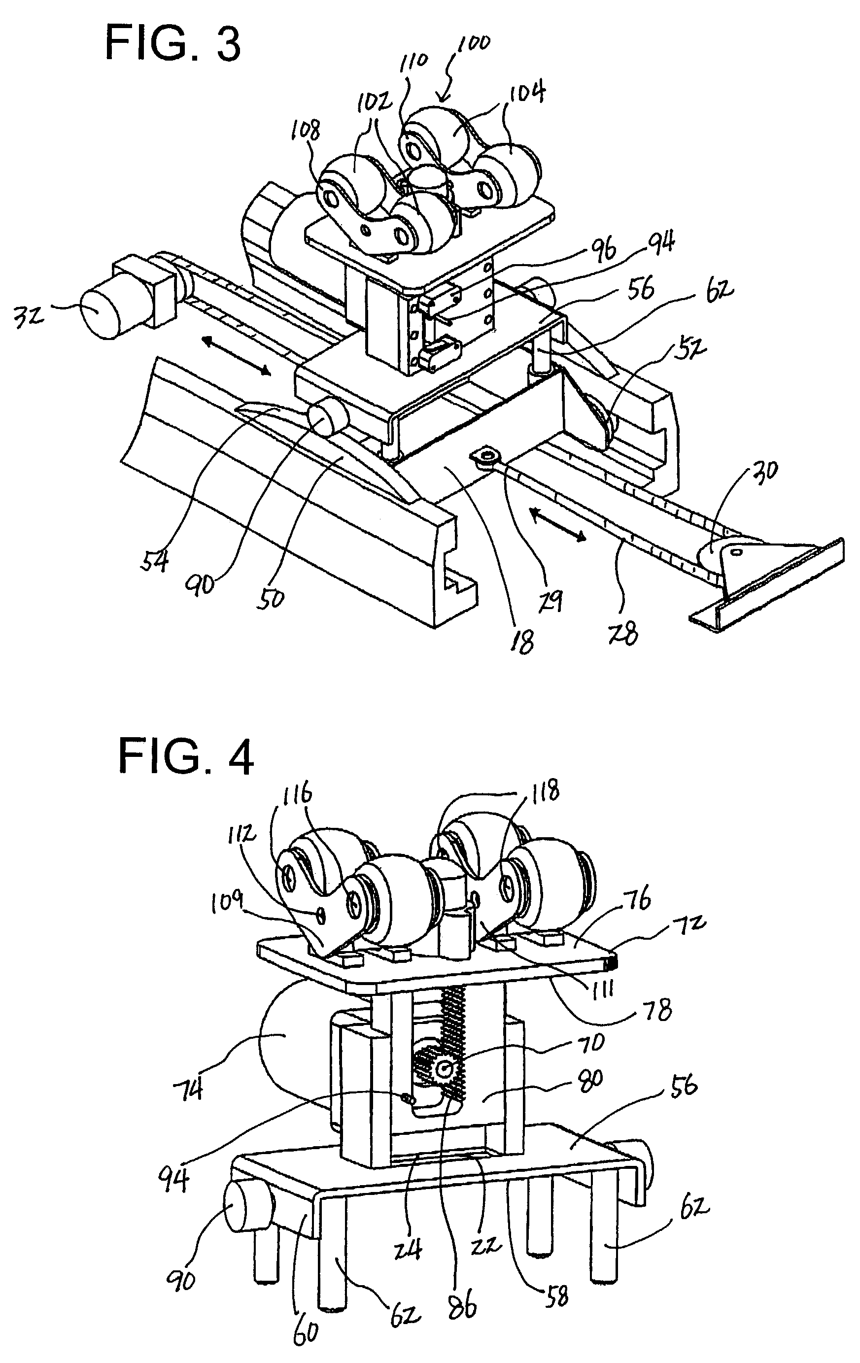
[0024]FIG. 1 shows a brief massaging mechanism of a lie-down massager 10 according to the present invention with a patient lying thereon for a bodily massage, and FIG. 2 shows a plan view of the massager 10 excluding the patient. As shown therein, the lie-down massager 10 includes a base frame 12 in a bed type or a mat type. The base frame 12 includes an elongated top panel 14, and an elongated opening 16 is formed centrally and lengthwisely through the elongated top panel 14. The massager 10 includes a rider 18 and a lifter 20. The rider 18 is provided below the elongated top panel 14 of the base frame 12. A rider opening 22 is formed vertically through the rider 18 to define an inner periphery 24 of the rider 18.

[0025]In order to implement the horizontal reciprocation of the rider 18, there is provided a guide member 26 movably engaged between the base frame 12 and the rider 18 so as to enable the rider 18 to make a horizontally reciprocal movement relative to the base frame 12. H...


PUM


Abstract

A lie-down massager comprises a frame having an elongated top panel with an elongated opening, a rider below the top panel, a guide member movably engaged between the frame and the rider to enable the rider to make a horizontal reciprocation relative to the frame, a lifter moving vertically relative to the rider, and a roller gear engaged to the rider. The roller gear is engaged to a vertical rack gear in an opening of an engagement body extending from the lifter so the roller gear rotation enables the lifter to make a vertical reciprocation. Massage bumps attached to the top portion of the lifter move vertically and / or horizontally along the elongated top opening of the elongated top panel of the frame by the lifter and the rider.

Description

BACKGROUND OF THE INVENTION[0001]The invention relates generally to a massaging device. More particularly, the present invention relates to an improved lie-down massager capable of efficiently treating bodily malfunctions such as back pain and gastrointestinal weakness by applying a therapeutic massaging treatment along the back and neck of a patient lying down on the massager whose massaging bumps move horizontally and vertically along the patient's spinal cord and neck while the vertical movement of the massaging bumps are actuated by a vertical rack gear mechanism.[0002]Conventional bed or mat type massaging devices employ a spring mechanism for vertically moving massaging bumps. As disclosed U.S. Pat. No. 6,454,732, a spring mechanism allows the massaging bumps to gently move up and down. However, when it comes to therapeutic effects, the spring mechanism proves too soft to push up the massaging bumps when stronger pressure is required, because tension of springs applies equally...

Claims


Application Information

Patent Timeline
Patent Type & Authority Patents(United States)
IPC IPC(8): A61H15/00A61H37/00
CPCA61H15/0078A61H2201/1669
Inventor KIM, HAKJIN
Owner SHIM 30 SIMON K
Why Eureka
Try Eureka