Over the shoulder holster belt

a holster belt and over-the-shoulder technology, applied in the field of holster belts, can solve the problems of not being suitable and quite conspicuous with electronic equipment, and achieve the effect of adapting to all sizes of cell phones

Inactive Publication Date: 2002-04-23
HENRI JACQUES
View PDF10 Cites 29 Cited by
  • Summary
  • Abstract
  • Description
  • Claims
  • Application Information

AI Technical Summary

Benefits of technology

A goal of the present invention is to provide a holster belt which will readily adapt to all sizes of cell phones.
Another object of the present invention is that the holster belt have a smooth outer surface, so as to be unobstrusive to the user.
A further object of the invention is that the holster assembly of the holster belt be positioned in such a position as not to affect in any way usual arm movements of the user, in particular during normal gait.
Another object of the invention is that the holster belt assembly be positioned in such a fashion as to enable the user's arm and chest to act as shields for protecting the cell phone or other article inside the holster assembly from external borne damage.
A further object of the invention is to make inconspicuous the cell phone inside the holster belt, when the user wears a jacket over the holster belt, so as to provide a suitable clothing attire which would be acceptable by peers for a variety of social environments.
An object of the invention is to allow the cell phone user to hear (or feel from vibration) an incoming call phone ring, wherein the holster assembly will not significantly dampen the sound generated by the phone.

Problems solved by technology

Such a shoulder holster as in the LUNDIE patent, is uncomfortable for the user during normal gait, where the user's arms will typically swing about back and forth, since the holster will come to chaff and eventually generate injuries to the user's inside arm.
However, in the EKMAN patent, the electronic equipment holster or pouch can fit only against the front chest or back of the wearer, not on the lateral side thereof.
This makes the electronic equipment quite conspicuous, which may not be appropriate in a number of social environments.

Method used


Image

  • Over the shoulder holster belt
  • Over the shoulder holster belt
  • Over the shoulder holster belt

Examples


Embodiment Construction

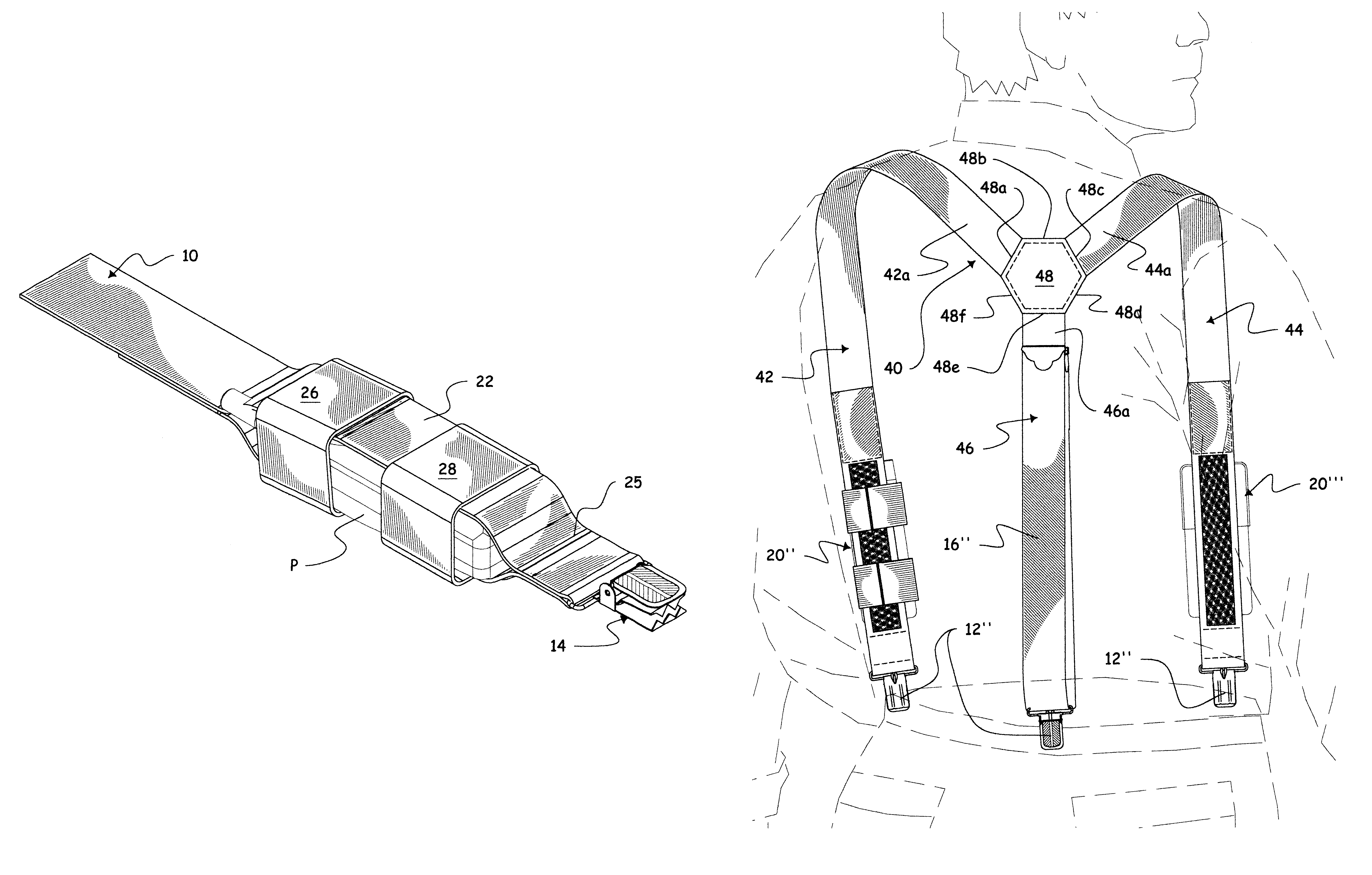
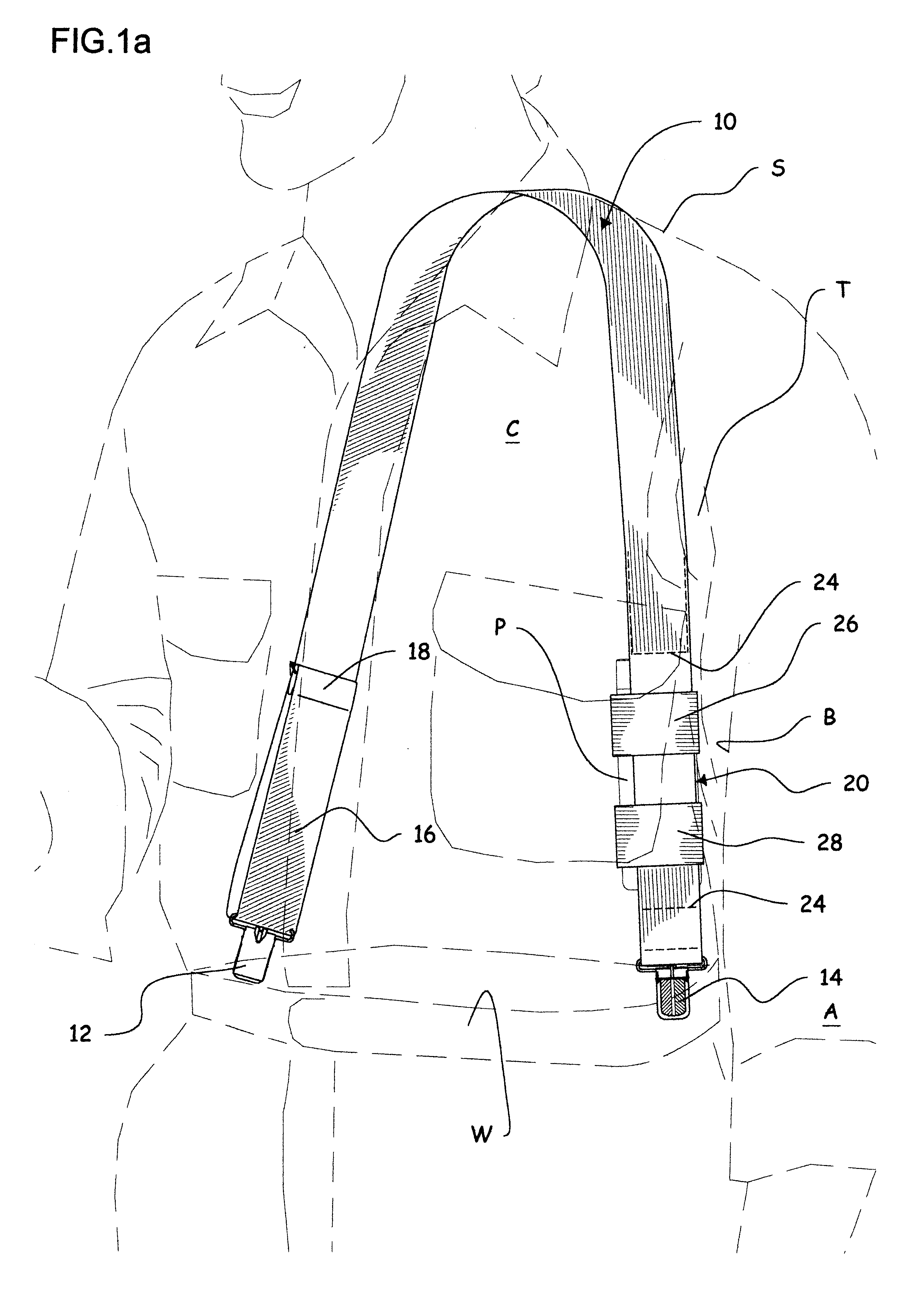
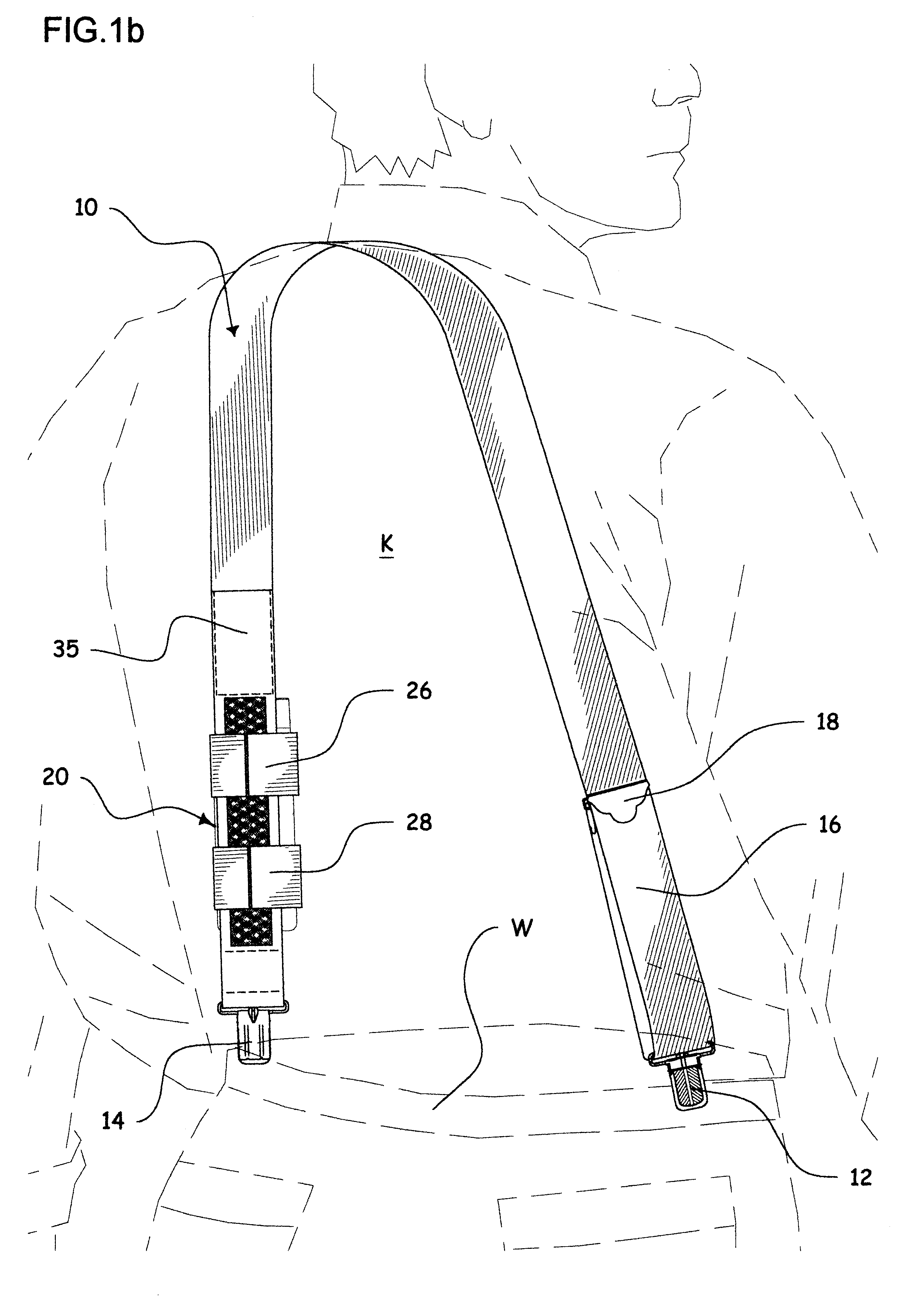
The invention consists of an elongated elastic band 10 having releasable hooking clamp buckles 12, 14, at its opposite ends. Elastic band 10 includes at its end portion proximate hooking clamp 12 a length adjustment loop 16, formed by an intermediate bracket 18 in the known fashion. Loop 16 is of variable length, depending on the size of the individual user chest C. Elastic band 10 also includes at its end portion proximate hooking clamp 14 (for example at about 2.5 cm therefrom) a holster assembly 20, for supporting and retaining an article such as a cell phone P, a cigar pack, or the like. Holster assembly 20 is formed by another belt loop 22 of the holster belt, with loop 22 being of permanently fixed length whereby permanent attachment means such as stitch lines 24 (see FIG. 3), are used to maintain constant this length of belt loop 22. Alternately, the length of the belt loop 22 is variable, with the stitch lines 24 being replaced by a hook and loop fastening adjusters 25 (see ...


PUM


Abstract

A holster belt for frictionally fitting over a shoulder and against the chest and back of an individual, said holster belt having: an elongated elastic band having releasable hooking first and second clamp buckles at its opposite ends for attachment to opposite sides of a wearer's waist belt, a generally open holster assembly, mounted at the end portion of said elastic band proximate said first clamp buckle for supporting and retaining a box-like article against the wearer's chest, said holster assembly formed by a belt loop of the holster belt; at least one elastic loop strip being transversely mounted to an intermediate section of said belt loop to accommodate and releasably retain against accidental release said box-like article.

Description

This invention relates to personal communication shoulder holsters that encircle the shoulder to support a small communication case.U.S. Pat. No. 5,358,159 issued in 1994 to Edgar LUNDIE, discloses a personal communication shoulder holster having a soft, flexible shoulder strap which encircles the shoulder with a size and shape to support side carriage of a small soft communication case under a user's arm. The should strap is adjustable in length and has resilient sections for adjustment and adaptability to body movement.Such a shoulder holster as in the LUNDIE patent, is uncomfortable for the user during normal gait, where the user's arms will typically swing about back and forth, since the holster will come to chaff and eventually generate injuries to the user's inside arm.U.S. Pat. No. 4,764,962 issued in 1988 to Joseph EKMAN et al, discloses a shoulder strap assembly having a pouch for supporting electronic audio equipment against the chest of a person. The shoulder strap assemb...

Claims


Application Information

Patent Timeline
Patent Type & Authority Patents(United States)
IPC IPC(8): A45F5/02A45F5/00A41D27/20A41F3/00A45F3/02A45F3/00H04B1/38
CPCA41D27/205A41F3/00A45F5/021A45F5/02A45F3/02A45F5/00H04B2001/3855A45F2200/0516H04B1/385
Inventor HENRI, JACQUES
Owner HENRI JACQUES
Why Eureka
Try Eureka