Ink jet head, manufacturing method therefor, and ink jet recording apparatus

a manufacturing method and ink jet technology, applied in the direction of printing, inking apparatus, etc., can solve the problem of increasing the cost and achieve the effect of high-quality alignment of ink jet heads

Inactive Publication Date: 2002-04-23
SEIKO EPSON CORP
View PDF10 Cites 17 Cited by
  • Summary
  • Abstract
  • Description
  • Claims
  • Application Information

AI Technical Summary

Benefits of technology

to provide an ink jet head in which highly accurate alignment of ink jet head chips is realized when a multi-nozzle structure is realized.

Problems solved by technology

Accordingly, the cost of an ink jet head is increased.

Method used


Image

  • Ink jet head, manufacturing method therefor, and ink jet recording apparatus
  • Ink jet head, manufacturing method therefor, and ink jet recording apparatus
  • Ink jet head, manufacturing method therefor, and ink jet recording apparatus

Examples


embodiment 1

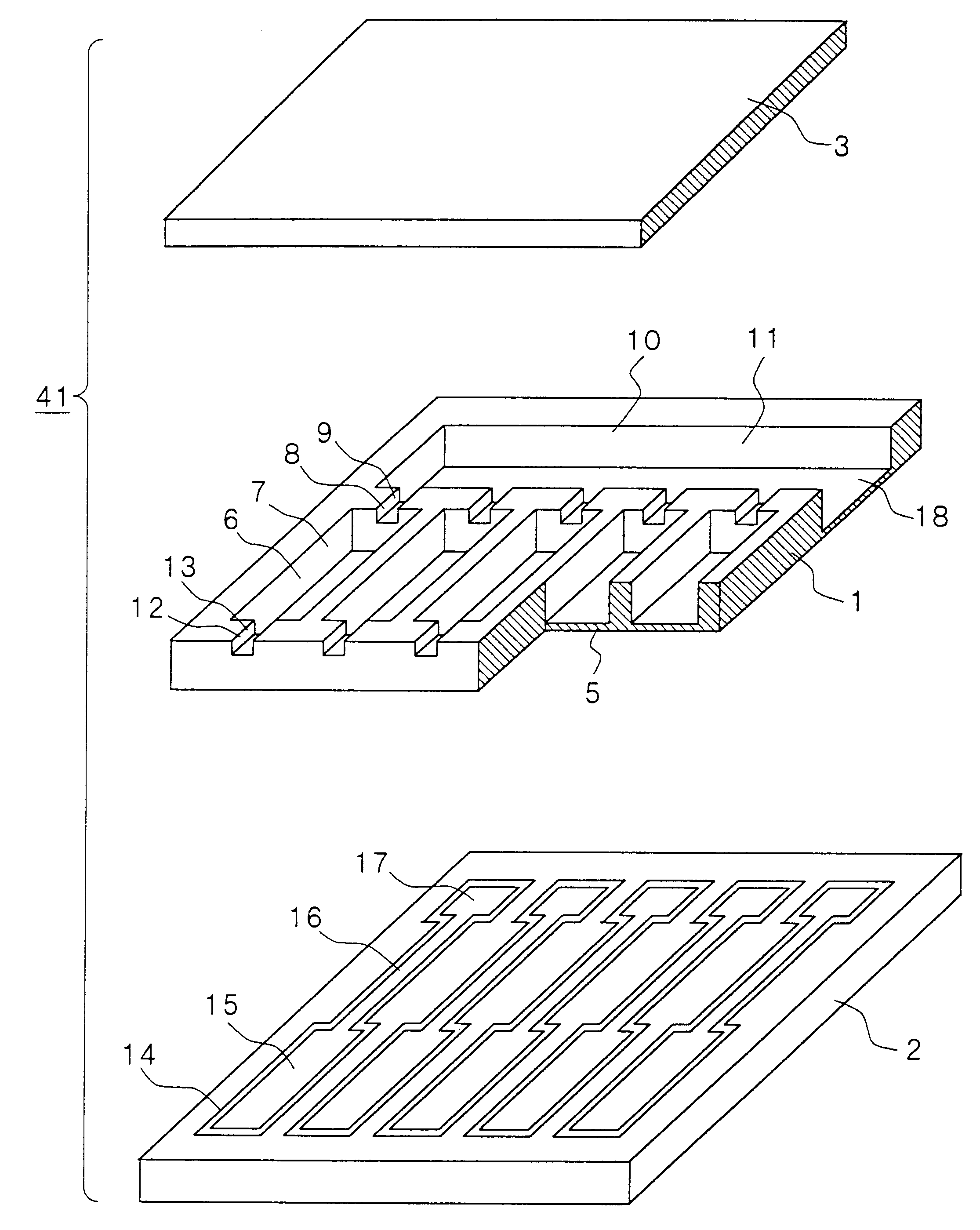
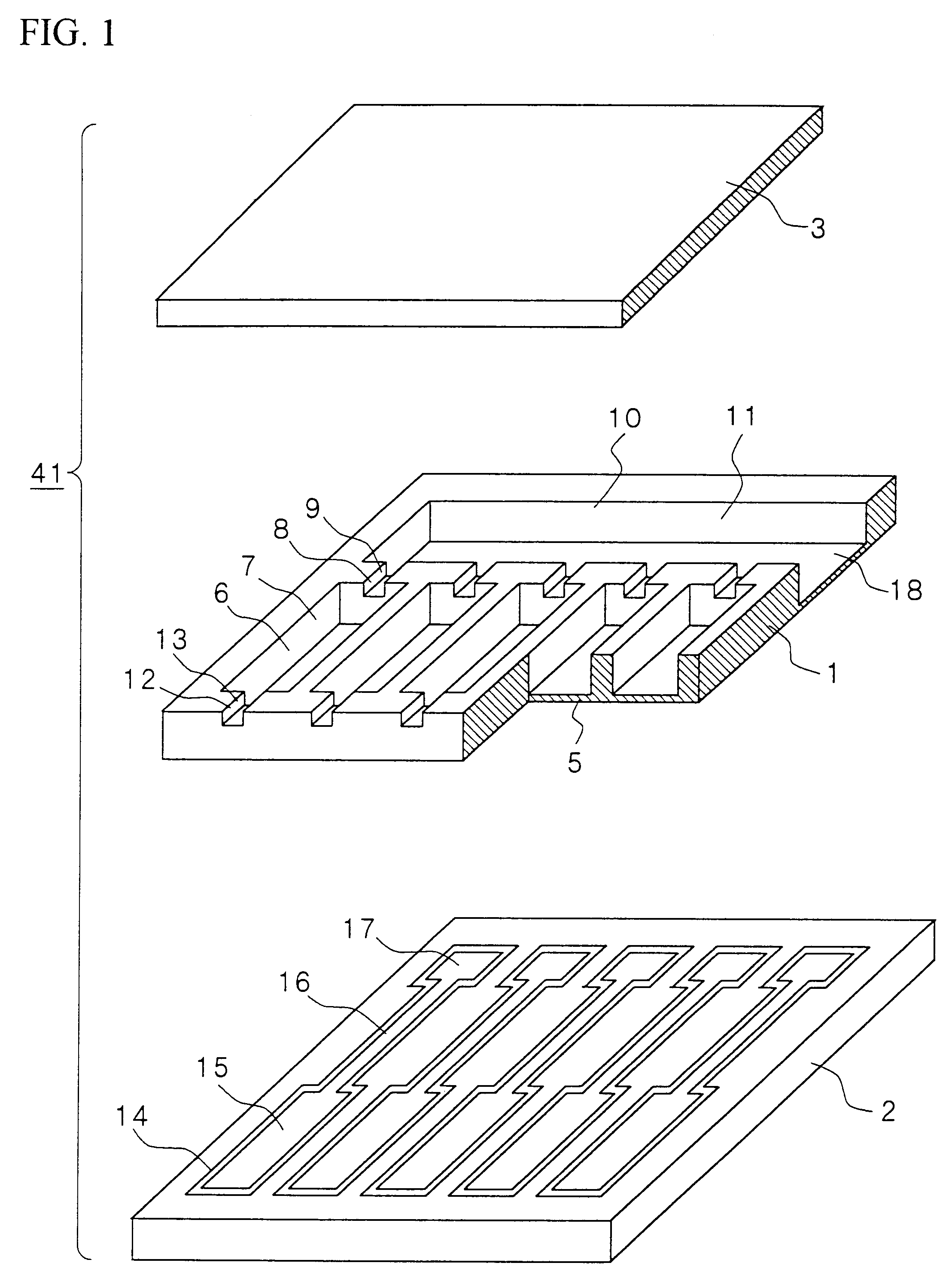
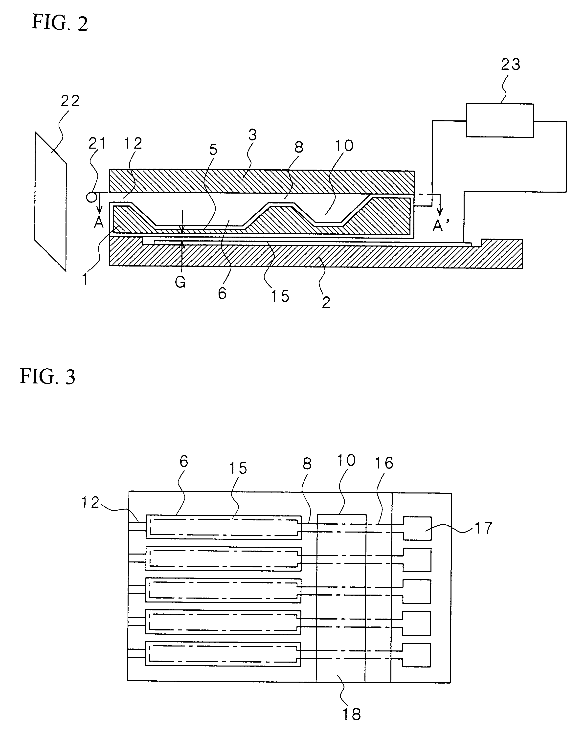
Of a stacked body of an ink jet head according to this embodiment 1, a single-layer portion (hereinafter referred to as "ink jet head chip") has a configuration as shown in FIGS. 1 and 2. This ink jet head chip is an edge eject type ejecting ink drops from nozzle holes provided in a head end portion.

The ink jet head chip in this embodiment 1 has a stacked structure in which three substrates 1, 2 and 3 have been stacked one on another and bonded with each other, as shown in FIGS. 1 and 2. The first substrate 1 in the middle is constituted by an Si substrate having recess portions 7 constituting ejection chambers 6 with their bottom wall acting as a diaphragm 5, narrow grooves 9 for ink inlets provided at the rear of the recess portions 7 so as to constitute orifices 8, and a recess portion 11 constituting a common ink cavity 10 for feeding ink to the respective ejection chambers 6. In addition, narrow grooves 13 constituting nozzle holes 12 are provided on the side opposite to the na...

embodiment 2

In an ink jet head according to this embodiment 2, grooves 51 which will be guides at the time of alignment are provided in nozzle surfaces 42 of ink jet head chips 41, as shown in FIG. 5. This ink jet head in FIG. 5 is assembled while it is positioned by pins 62 of an alignment jig 61, as shown in FIGS. 6 and 7.

The alignment jig 61 is included in an alignment device in FIG. 8 in advance. An alignment case 201 is opened in its upper portion, and provided with windows 202 and 203 in its side portion. Partition portions 204 shaped into projecting strips for determining the intervals of the ink jet head chips 41 are provided in the inner wall of the side portion. Clamping plates 205 and 206 are fitted into the windows 202 and 203. A porous rubber pad (hard) 206 is provided on the inner wall of one clamping plate 205, while a porous rubber pad (soft) 208 is provided on the inner wall of the other clamping plate 207. In addition, the alignment jig 61 is disposed on the bottom portion of ...

embodiment 3

In an ink jet head according to this embodiment 3, grooves 81 which will be guides at the time of alignment are provided in side surfaces 43 of ink jet head chips 41, as shown in FIG. 9. This ink jet head in FIG. 9 is assembled while it is positioned by alignment plates 92 of alignment jigs 91 shown in FIG. 10.

The alignment jigs 91 are included in an alignment device in FIG. 11 in advance. An alignment case 201 is opened in its upper portion, and provided with windows 202 and 203 in its side portion. Partition portions 204 shaped into projecting strips for determining the intervals of the ink jet head chips 41 are provided in the inner wall of the side portion. The alignment jigs 91 are fitted into the windows 202 and 203. The alignment plates 92 are provided on the inner wall of each of these jigs 91. In addition, a smooth plate 211 for truing up the nozzle surfaces 42 is disposed on the bottom portion of the alignment case 201.

When the ink jet head chips 41 are positioned as shown...


PUM


Abstract

An ink jet head in which a multi-nozzle structure is attained, and highly accurate alignment of ink jet head chips is realized, a method for manufacturing the ink jet head, and a recording apparatus on which the ink jet head is mounted. Guide protrusions (141) for alignment of ink jet head chips (41) are formed in an ink jet head chip bonded surface (134) of a nozzle plate (133), the ink jet head chips (41) are aligned by inserting the guide protrusions (141) of the nozzle plate (133) into guide grooves (51) of nozzle surfaces (42) of the ink jet head chips (41), and the nozzle plate (133) and the respective ink jet head chips (41) are bonded with each other by a bonding agent.

Description

The present invention relates to an ink jet head which is a main part of an ink jet head recording apparatus ejecting ink drops to thereby attach the ink drops onto recording paper only when recording is required; a manufacturing method therefor; and the ink jet recording apparatus.BACKGROUND TECHNIQUEAn ink jet recording apparatus has many advantages in that noise is extremely small at the time of recording, printing can be performed at a high speed, freedom of ink is high so that inexpensive cheap ordinary paper can be used, and so on. Of the apparatus, a so-called ink-on-demand system ejecting ink drops only when recording is required is becoming the mainstream currently because it is not necessary to recover ink drops unnecessary for recording.One type of ink jet recording apparatus adopting this ink-on-demand system has an ink jet head in a system using electrostatic power (e.g. JP-A-6-71882) as a driving system for ejecting ink. This system has advantages in that it is small i...

Claims


Application Information

Patent Timeline
Patent Type & Authority Patents(United States)
IPC IPC(8): B41J2/14B41J2/16
CPCB41J2/14233B41J2/14314B41J2/161B41J2/1623B41J2/1628B41J2/1631B41J2/1646B41J2/1629B41J2202/19B41J2002/14362B41J2002/14379
Inventor ARAKAWA, KATSUJIKOEDA, HIROSHI
Owner SEIKO EPSON CORP
Why Eureka
Try Eureka