Probe unit and its manufacture

a technology of probe pins and probe pins, which is applied in the field of probe pins, can solve the problems of difficult to form a probe unit compatible with such a pitch, difficult to adhere leads to an insulating base at a high precision of position alignment, and difficulty in forming a probe unit, so as to improve the position precision of the probe pins relative to the electrodes of the test body, and improve the accuracy of the position alignment of the probe pins

Inactive Publication Date: 2006-02-14
YAMAICHI ELECTRONICS
View PDF12 Cites 13 Cited by
  • Summary
  • Abstract
  • Description
  • Claims
  • Application Information

AI Technical Summary

Benefits of technology

[0023]The positioning member may have the inner clip washer shape that elastic protrusions extend circumferentially around a through hole formed through the substrate. By pressure-fitting a member for positioning the substrate relative to the probe device into the positioning member having the inner clip washer shape, the position precision of the probe pins relative to the probe device can be improved further because of a centering function of the positioning member.
[0033]Since the probe pins and positioning member are formed at the same time by lithography, a position precision of relative positions of the probe pins and positioning member can be improved. As the substrate is positioned and fixed to the probe device by using the positioning member as a position reference, the probe pins are positioned on the probe device at a high precision. According to the probe unit manufacture method, a position precision of the probe pins relative to electrodes of the test body can be improved.
[0035]Since the probe pins and positioning member are formed by lithography by using the common alignment mark as a position reference, a position precision of relative positions of the probe pins and positioning member can be improved. As the substrate is positioned and fixed to the probe device by using the positioning member as a position reference, the probe pins are positioned on the probe device at a high precision. According to the probe unit manufacture method, a position precision of the probe pins relative to electrodes of the test body can be improved. Either the process of forming the probe pins or the process of forming the positioning member may be performed first after the alignment mark is formed.
[0037]Since the positioning member is formed by using as a position reference the alignment mark formed at the same time when the probe pins are formed, a position precision of relative positions of the probe pins and positioning member can be improved. As the substrate is positioned and fixed to the probe device by using the positioning member as a position reference, the probe pins are positioned on the probe device at a high precision. According to the probe unit manufacture method, a position precision of the probe pins relative to electrodes of the test body can be improved.
[0039]Since the probe pins are formed by using as a position reference the alignment mark formed at the same time when the positioning member is formed, a position precision of relative positions of the probe pins and positioning member can be improved. As the substrate is positioned and fixed to the probe device by using the positioning member as a position reference, the probe pins are positioned on the probe device at a high precision. According to the probe unit manufacture method, a position precision of the probe pins relative to electrodes of the test body can be improved.
[0043]The probe unit can be mounted on each of various apparatuses such as test bodies at a high precision of position alignment. A conduction test for a liquid crystal display panel or the like can be performed at a high precision. Since a pattern for determining a mount position and probe pins can be formed at the same time, positioning holes can be formed at a high precision. A precision of relative positions of the probe pins and a test body can be improved.

Problems solved by technology

It is difficult to form a probe unit compatible with such a pitch through mechanical punching.
Narrow pitches of electrodes of a test body and probe pins make it difficult to realize position alignment between the electrodes and probe pins.
With the method described in Japanese Patent Publication No. 2552084, however, it is very difficult to adhere leads to an insulating base at a high precision of position alignment.
In addition, when tie bars are cut, leads may be damaged.
With the method described in JP-B-7-56493, it is very difficult to adhere conductive contact terminals to the insulating member at a high precision of position alignment.
With the method described in JP-A-11-337575, the thin plated copper seed layer has a small contact area with solvent so that it is hard to dissolve the seed layer and it takes a long time to separate the probe pins.
It is also difficult to form holes through a substrate with a drill or a laser at a high precision and to dispose the probe pins at positions corresponding to the holes.
It is therefore difficult to realize a high position alignment precision between probe pins and positioning holes.
It is therefore difficult to obtain sufficiently high position precision between the probe device and probe pins and between electrodes of a test body held by the probe device and probe pins.

Method used


Image

  • Probe unit and its manufacture
  • Probe unit and its manufacture
  • Probe unit and its manufacture

Examples


Embodiment Construction

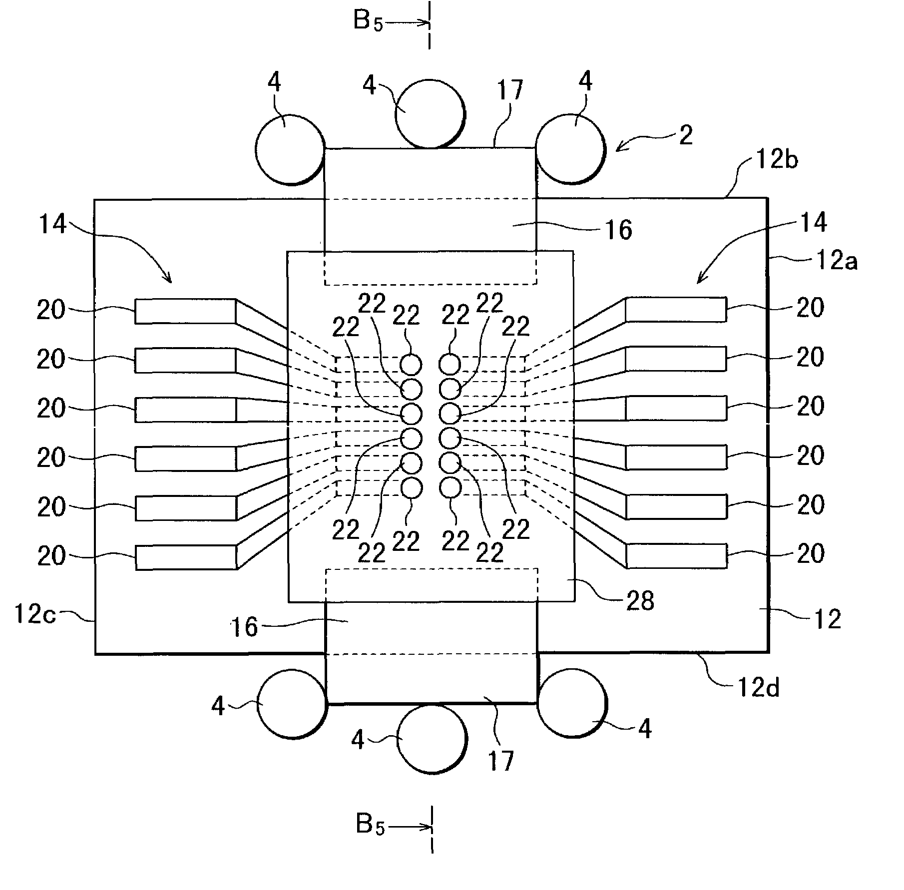
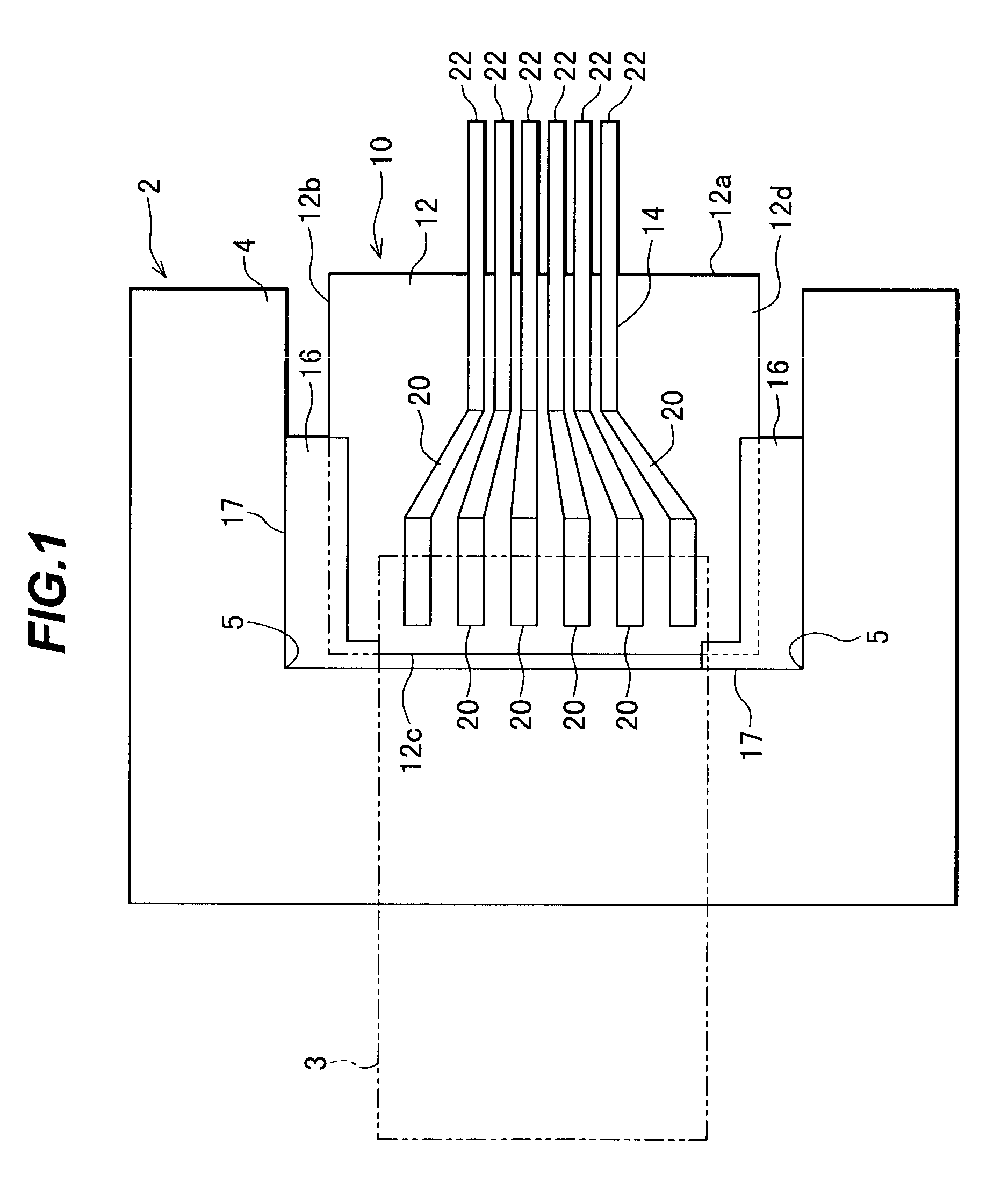
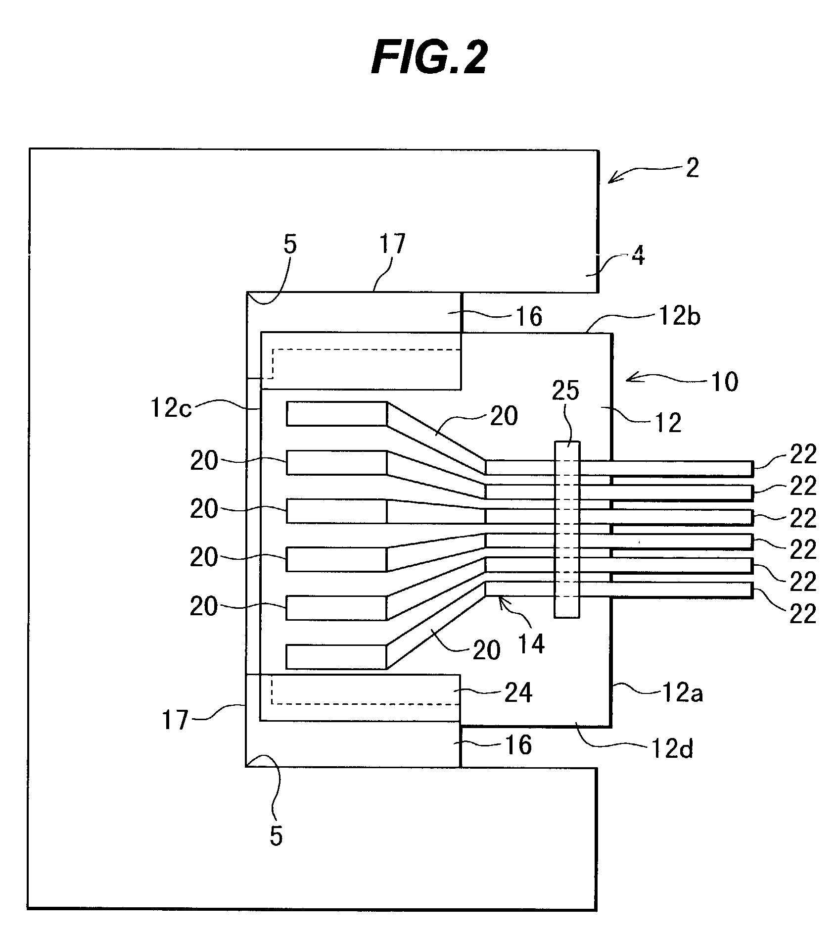
[0073]Description will be made on the preferred embodiments of the invention, referring to the drawings. Probe units according to the embodiments of the invention will be described. First to fifth structures of a probe unit 10 shown in FIGS. 1 to 5B will be described first. The probe unit 10 has a lead pattern 14 and positioning members 16 formed on a substrate 12. The probe unit 10 is fixed to a probe device 2 positioned above a test body base (sample base). In the examples shown in FIGS. 1 to 5B, although one probe unit 10 is fixed to the probe device 2, the number of probe units to be fixed to the probe device 2 is determined depending upon the structure of a test body. For example, four probe units may be fixed radially at a pitch of 90° to a probe device.

[0074]The substrate 12 is made of generally a rectangular plate. Material of the substrate 12 may be insulating material such as glass ceramic, quartz, zirconia, glass, alumina and synthetic resin, or conductive material such a...


PUM


Abstract

A probe unit to be fixed to a probe device for testing functions of a test body. The probe unit includes: a substrate; probe pins formed on the substrate by lithography, the probe pins having distal ends protruded from the substrate and being made in contact with electrodes of the test body; and a positioning member formed on the substrate by lithography at a predetermined position relative to the probe pins, the positioning means abutting upon a member for positioning the substrate relative to the probe device.

Description

CROSS REFERENCE TO RELATED APPLICATION[0001]This application is based on Japanese Patent Applications No. 2001-287088, filed on Sep. 20, 2001, No. 2002-164244, filed on Jun. 5, 2002, and No. 2002-205285, filed on Jul. 15, 2002, the entire contents of which are incorporated herein by reference.BACKGROUND OF THE INVENTION[0002]A) Field of the Invention[0003]The present invention relates to a probe unit and its manufacture, the probe unit being used for conduction tests of electrodes, terminals and the like of an electronic device (test body) such as a semiconductor integrated circuit and a liquid crystal display panel.[0004]B) Description of the Related Art[0005]A conduction test is generally performed for products such as semiconductor integrated circuits, liquid crystal display panels and printed circuit boards in order to check whether these products can operate satisfactorily meeting the requirements of specifications.[0006]During this conduction test, probe pins formed at or near...

Claims


Application Information

Patent Timeline
Patent Type & Authority Patents(United States)
IPC IPC(8): G01R31/02G01R1/067
CPCG01R1/067
Inventor TERADA, YOSHIKISAWADA, SHUICHIHATTORI, ATSUO
Owner YAMAICHI ELECTRONICS
Why Eureka
Try Eureka