Method of manufacturing optical sensor module and optical sensor module obtained thereby

a manufacturing method and sensor technology, applied in the field of manufacturing optical sensor modules and optical sensor modules obtained thereby, can solve the problems of unsuitable mass production, unsuitable for mass production, and still has room for improvement in alignment accuracy and cost, and achieves the effect of simple positioning structur

Inactive Publication Date: 2011-04-14
NITTO DENKO CORP
View PDF23 Cites 15 Cited by
  • Summary
  • Abstract
  • Description
  • Claims
  • Application Information

AI Technical Summary

Benefits of technology

[0017]In particular, when the above-mentioned positioning member of the above-mentioned optical waveguide section are in the form of protruding portions of a generally U-shaped plan configuration or of an L-shaped plan configuration and the above-mentioned to-be-positioned portions of the above-mentioned substrate section are in the form of plate portions for abutment against the inside surfaces of the above-mentioned protruding portions, then the optical sensor module kept in high-precision alignment by a simple positioning structure is provided.
[0018]Also, when the above-mentioned fitting portions of the above-mentioned optical waveguide section are in the form of groove portions extending across the thickness of the over cladding layer, and the width of portions of the groove portions corresponding to an upper surface portion of the over cladding layer decreases gradually in a downward direction from the upper surface of the over cladding layer, when the above-mentioned to-be-fitted portions of the above-mentioned substrate section are in the form of plate portions for fitting engagement with the above-mentioned groove portions, when the above-mentioned positioning member of the above-mentioned optical waveguide section are in the form of protruding portions of a generally U-shaped plan configuration, and the width of a generally U-shaped opening portion of the protruding portions decreases gradually in an inward direction from the opening end thereof, and when the above-mentioned to-be-positioned portions of the above-mentioned substrate section are in the form of plate portions for abutment against the inside surfaces of the above-mentioned protruding portions, then the optical sensor module kept in high-precision alignment by a simple positioning structure is provided.

Problems solved by technology

While the alignment using the above-mentioned self-aligning machine can be high-precision alignment, it requires labor and time and is therefore unsuited for mass production.
However, the above-mentioned method still has room for improvement in alignment accuracy and in costs.
This results in the increase in the cost of the light-emitting element.
This results in the increase in the cost of the molding die.

Method used


Image

  • Method of manufacturing optical sensor module and optical sensor module obtained thereby
  • Method of manufacturing optical sensor module and optical sensor module obtained thereby
  • Method of manufacturing optical sensor module and optical sensor module obtained thereby

Examples


##ventive example 1

Inventive Example 1

Production of Optical Waveguide Section

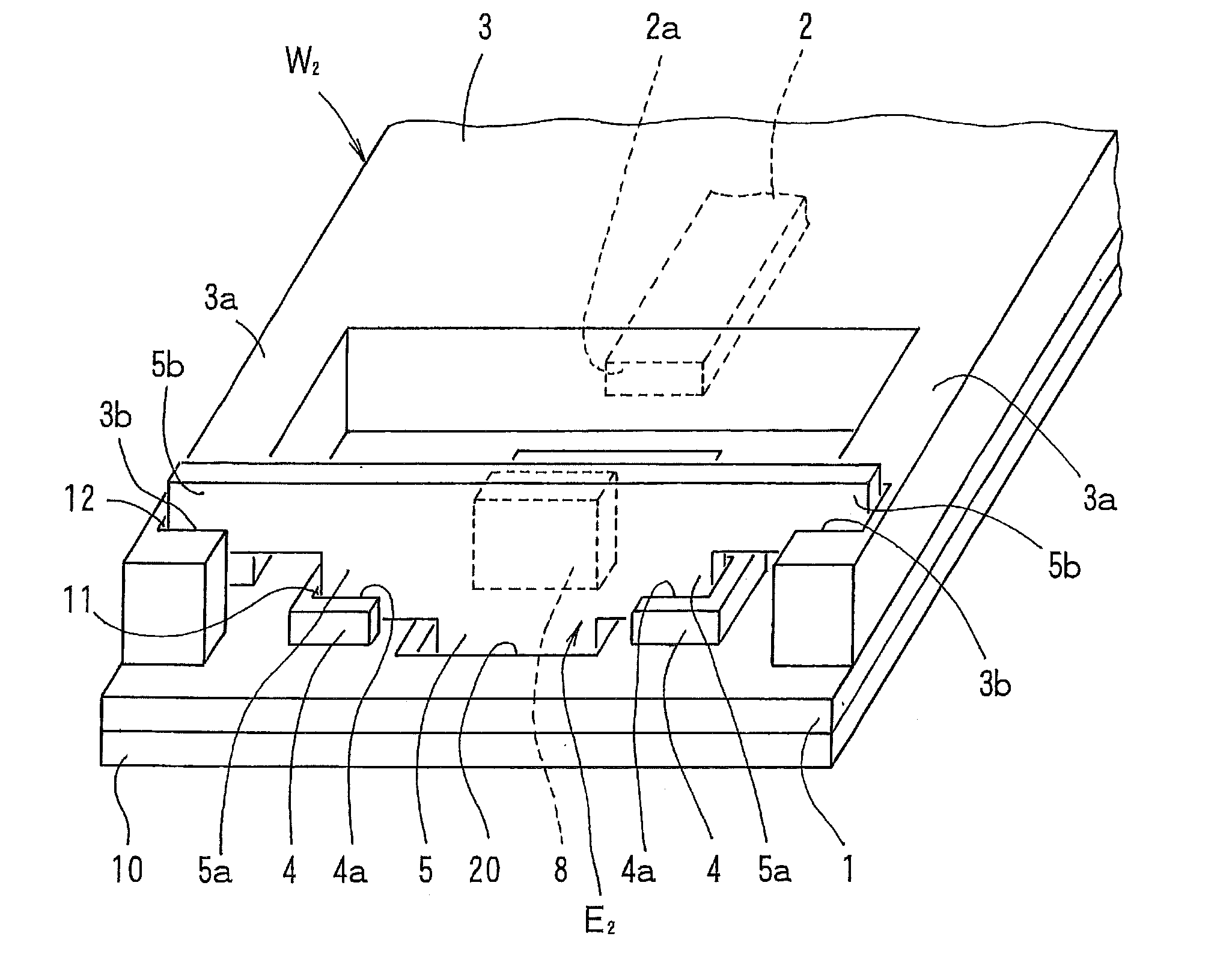
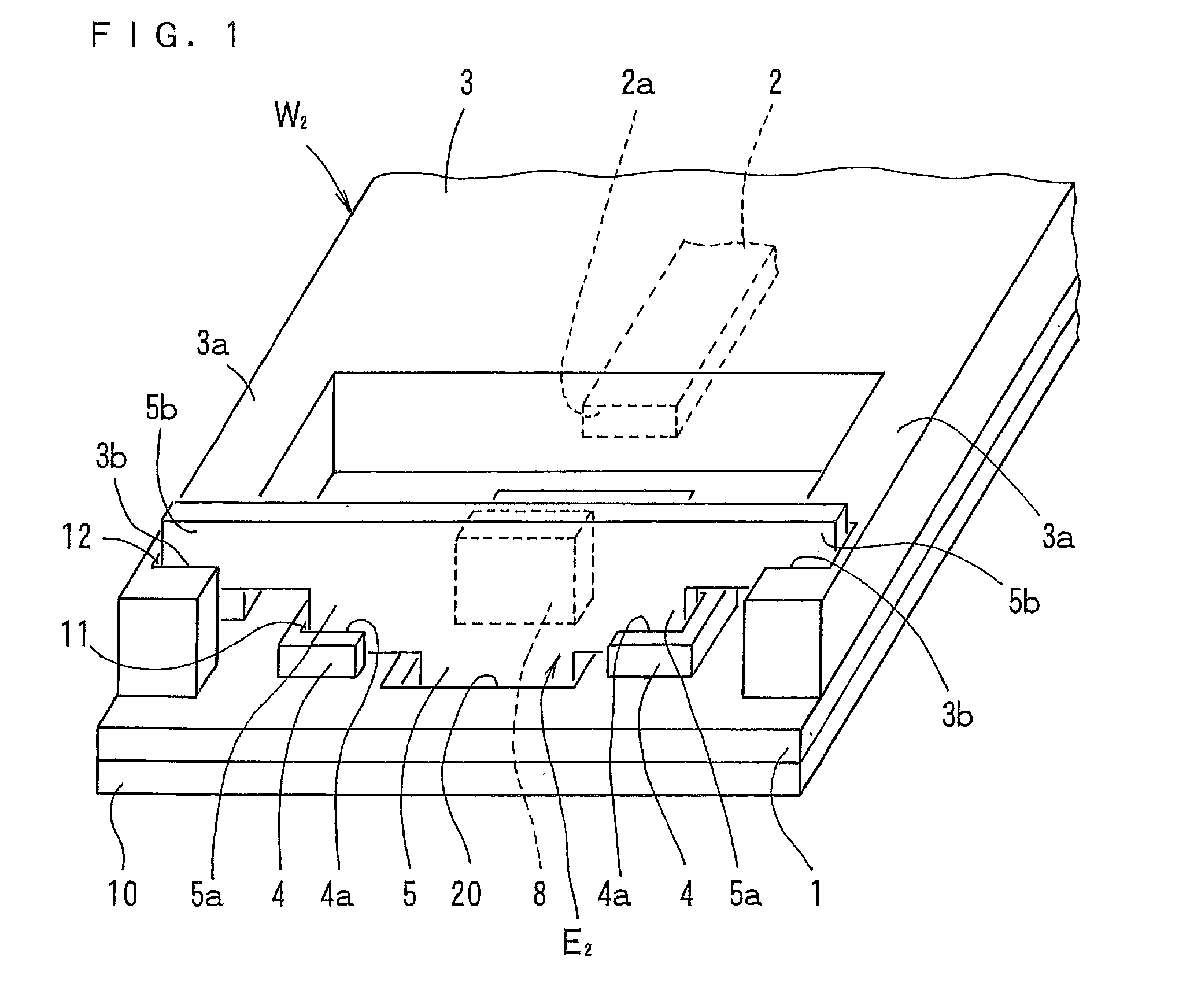
[0084]The material for the formation of the above-mentioned under cladding layer was applied to a surface of a sheet material made of stainless steel (having a thickness of 50 μm) with an applicator. Thereafter, exposure by the use of irradiation with ultraviolet light (having a wavelength of 365 nm) at 2000 mJ / cm2 was performed, to thereby form the under cladding layer (having a thickness of 20 μm) (with reference to FIG. 5A).

[0085]Then, the material for the formation of the above-mentioned core and the protruding portions was applied to a surface of the above-mentioned under cladding layer with an applicator. Thereafter, a drying process was performed at 100° C. for 15 minutes to form a photosensitive resin layer (with reference to FIG. 5B). Next, a synthetic quartz chrome mask (photomask) formed with an opening pattern identical in shape with the pattern of the core and the protruding portions were placed over the photosen...

##ventive example 2

Inventive Example 2

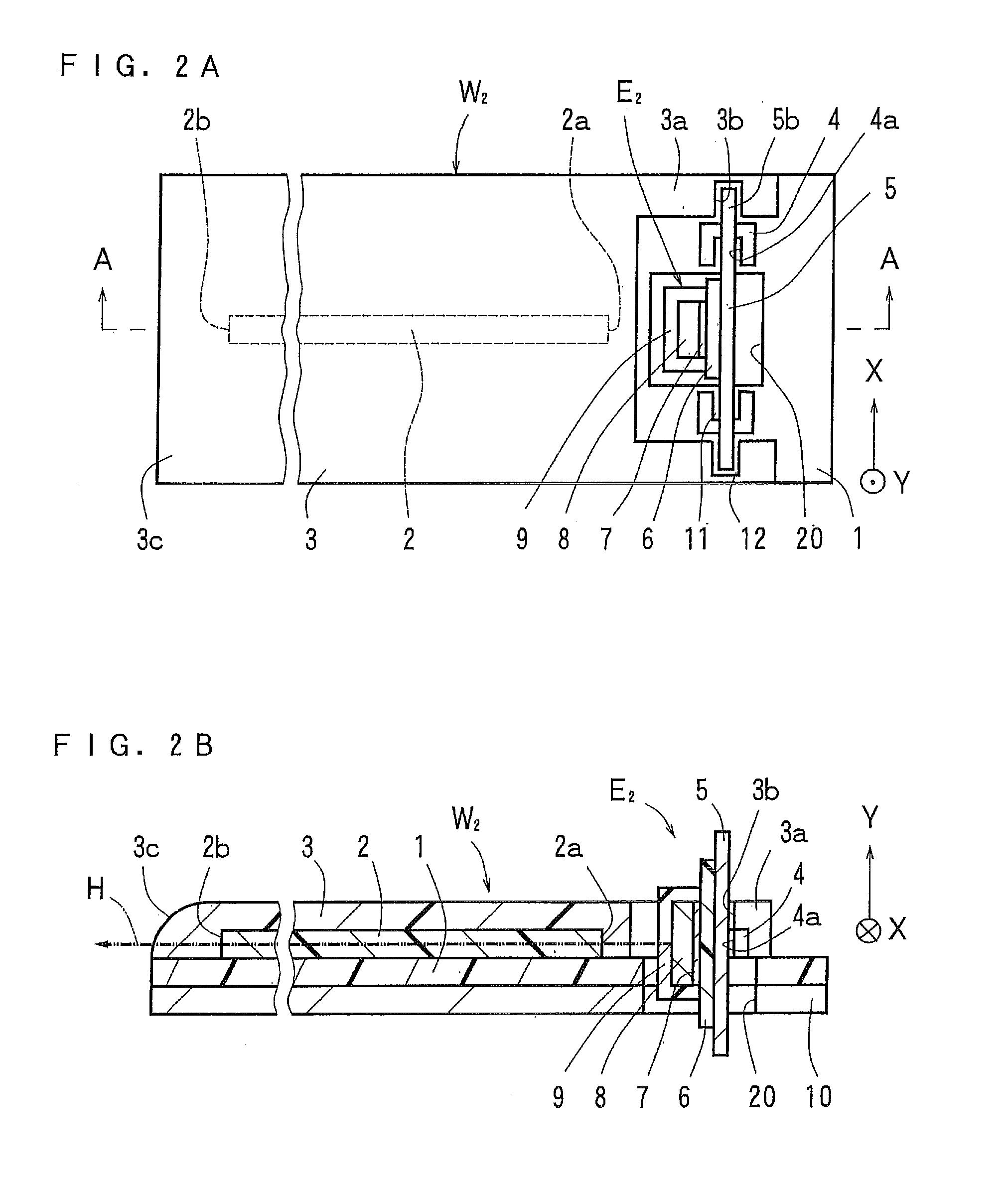
[0091]Portions of the pair of groove portions corresponding to an upper surface portion of the over cladding layer in Inventive Example 1 described above were formed as tapered portions (with reference to FIG. 8). The dimensions of the groove portions were shown in FIGS. 10A and 10B. FIGS. 10A and 10B showed the groove portion 14 having the greater depth (a depth of 5.0 mm). The groove portion 13 having the smaller depth (with reference to FIG. 8) had a depth of 3.0 mm. The remaining dimensions of the groove portion 13 were similar to those of the groove portion 14 having the greater depth. Of the pair of protruding portions 15 and 16, as shown in FIG. 10C, the protruding portion (left-hand as seen in the FIG. 15 closer to the grove portion 13 having the smaller depth was formed in a generally U-shaped plan configuration, and had a generally U-shaped opening portion in the form of the tapered portion 15a, whereas the protruding portion (right-hand as seen in the F...


PUM


Abstract

A method of manufacturing an optical sensor module which eliminates the need for the operation of alignment between a core in an optical waveguide section and an optical element in a substrate section and which achieves improvement in alignment accuracy and reduction in costs, and an optical sensor module obtained thereby. An optical waveguide section W2 including protruding portions 4 for the positioning of a substrate section and groove portions 3b for fitting engagement with the substrate section, and a substrate section E2 including positioning plate portions 5a to be positioned in the protruding portions 4 and fitting plate portions 5b for fitting engagement with the groove portions 3b are individually produced.

Description

RELATED APPLICATIONS[0001]This application claims the benefit of U.S. Provisional Application No. 61 / 254,796, filed Oct. 26, 2009, which is hereby incorporated by reference.BACKGROUND OF THE INVENTION[0002]1. Field of the Invention[0003]The present invention relates to a method of manufacturing an optical sensor module including an optical waveguide section and a substrate section with an optical element mounted therein, and to an optical sensor module obtained thereby.[0004]2. Description of the Related Art[0005]As shown in FIGS. 11A and 11B, an optical sensor module is manufactured by: individually producing an optical waveguide section W0 in which an under cladding layer 71, a core 72 and an over cladding layer 73 are disposed in the order named, and a substrate section E0 in which an optical element 82 is mounted on a substrate 81; and then connecting the above-mentioned substrate section E0 to an end portion of the above-mentioned optical waveguide section W0, with the core 72 ...

Claims


Application Information

Patent Timeline
Patent Type & Authority Applications(United States)
IPC IPC(8): G02B6/02G02B6/26
CPCG02B6/423G02B6/42
Inventor HODONO, MASAYUKI
Owner NITTO DENKO CORP
Why Eureka
Try Eureka